Manual cal, 1 preparation before calibration, 2 operating the span gas flow setting valve – Yokogawa Multi Channel Oxygen Analyzer System ZR22/AV550G User Manual
Page 193
IM 11M12D01-01E
10-31
10. Other Functions
10.8
Methods of Operating Valves in the ZA8F Flow Setting Unit
The ZA8F Flow Setting Unit is used for manual calibration as described in Section
1.1.1. Calibration in such a system is to be manually operated. So, you have to operate
the valve of the Flow Setting each time calibration is made (starting and stopping the
calibration gas flow and adjusting the flow rate). This applies even if you are using the
ZR40H Autocalibration Unit. For operation of the converter, see Section 7.12, earlier in
this manual.
10.8.1
Preparation Before Calibration
To operate the ZA8F Flow Setting Unit, prepare for calibration as follows:
(1) Check for a complete closing of the zero gas flow setting valve in the unit and open
the regulator valve for the zero gas cylinder until the secondary pressure equals
measured gas pressure + approx 50 kPa (or measured gas pressure plus approx. 150
kPa when a check valve is used, maximum pressure rating is 300 kPa).
(2) Check that the oxygen concentration of the zero gas and span gas (instrument air 21
vol% O
2
) in the cylinder is set in the converter.
10.8.2
Operating the Span Gas Flow Setting Valve
The following description is given assuming that instrument air, the same as the refer-
ence gas, is used as the span gas.
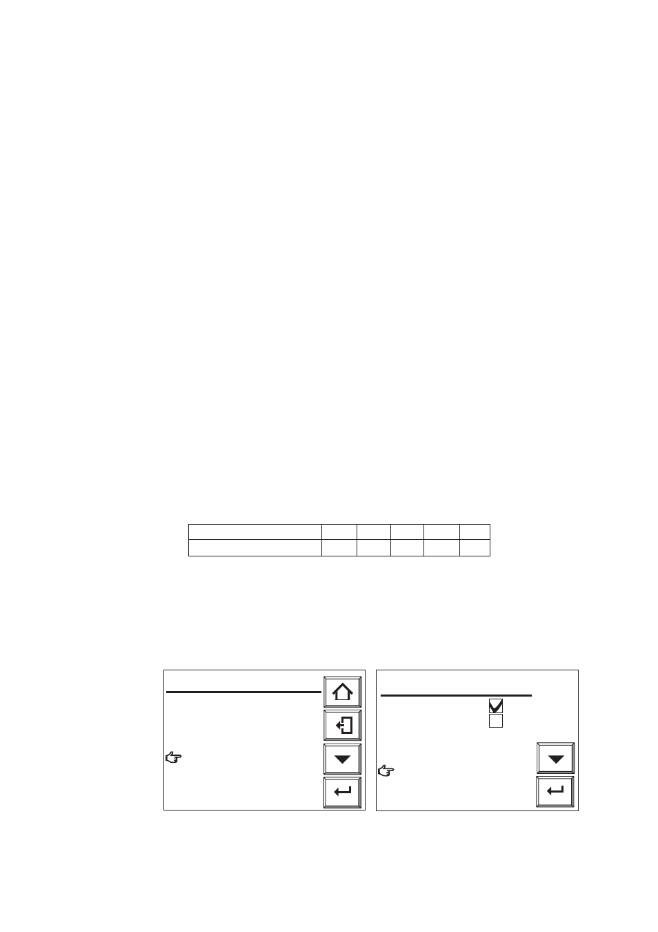
(1) When the display shown in Figure 10.33 appears during calibration, open the span
gas flow setting valve of the flow setting unit and adjust the flow rate to 600 ml/min
±
60 ml/min. Turn the valve slowly counterclockwise after loosening the lock nut if
the valve has a lock nut. To check the flow rate, use the calibration flow meter. If the
measurement gas pressure is extremely high, adjust the measurement gas pressure to
obtain pressures (listed in Table 10.6)
±
10%.
Table 10.10
Measurement gas pressure (kPa) 50 100 150 200 250
Flowrate (ml/min) 500 430 380 250 320
T10.10E.EPS
(2) Adjust the flow rate and select Valve opened from the Manual calibration display.
Check the Trend graph display to see that the measured value is stabilized. Then
press the [Enter] key. The Manual calibration display shown in Figure 10.34 appears.
Close the span gas flow setting valve to stop the span gas (air) flow. If the valve has
a lock nut, be sure to tighten the lock nut to prevent any leakage of span gas into the
sensor during measurement.
Enter
F22E.EPS
Ch1
Manual cal.
Open span gas valve.
Set flow span gas to
600ml/min.
Valve opened
᭜
Cancel calibration
Enter
F24E.EPS
Ch1
Manual cal.
Span calibration
Zero calibration
Zero calibration
᭜
End
Close the span gas valve.
Fig. 10.33 Fig.10.34