7 zero gas cylinder (part no. g7001zc), 2 piping for the calibration gases – Yokogawa Multi Channel Oxygen Analyzer System ZR22/AV550G User Manual
Page 77
IM 11M12D01-01E
4-11
4. Piping
4.2.2
Piping for the Calibration Gases
The piping for the calibration gases should be installed between the calibration gas
cylinders (or instrument air source) and the detectors with a flowmeter, solenoid valves,
needle valves, and stop valves for performing automatic calibration.
• Place the calibration gas cylinders in a place not exposed to direct sunlight as much as
possible, e.g., house in a gas unit case. The cylinder should be equipped with a
pressure reducing valve (Yokogawa recommended part) and where necessary, a stop
valve.
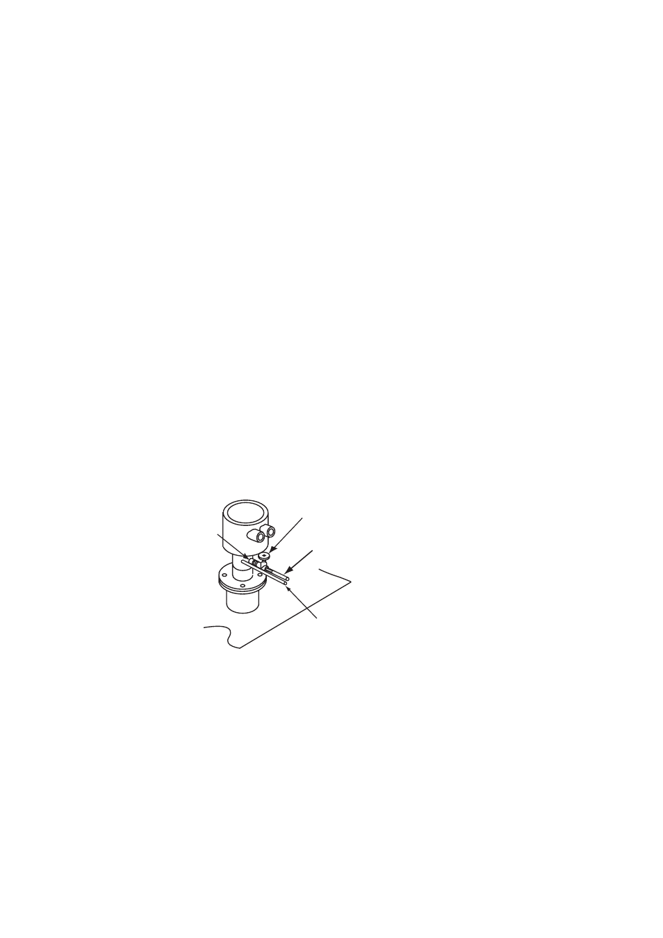
• Install a normally closed solenoid valve (Yokogawa recommended part) through a
nipple (commercially available) on the calibration gas inlet of the detector as shown
in Figure 4.11. This solenoid valve is activated by a contact signal from the averaging
converter. (Power wiring is separately required.)
Note: If the solenoid valve cannot be connected directly to the calibration gas inlet of
the detector, install a dedicated check valve (K9292DN or K9292DS) on the
inlet and then route the piping to the solenoid valve.
• After installing the solenoid valve on the calibration gas inlet of the detector, route the
piping through a flowmeter, a needle valve, a solenoid valve for switching zero and
span gases, a stop valve, and a pressure reducing valve for the cylinder, in this order,
to the cylinder.
• Install the piping for the solenoid valve for switching zero and span gases so that the
zero gas is introduced to the detector when powered. This solenoid valve is activated
by a contact signal from the averaging converter. (Power wiring is separately
required.)
• Install the needle valve and flowmeter in close proximity as much as possible.
• Use stainless steel pipes with 6 OD x 4 ID mm (or nominal 1/4 inch) or larger inside
diameter for the piping for the calibration gases.
F4202.EPS
Solenoid valve (nomal close)
Connect directly to piping inlet
Calibration gas piping
л
6
ϫ л
4mm stainless steel pipe
Reference gas piping
л
6
ϫ л
4mm
(or nominal 1/4-inch) stainless steel pipe
Nipple
Figure 4.11 Piping for the Calibration Gas Inlet