5 check valve (part no. k9292dn or k9292ds), 4 mounting of the high-temperature detector, Figure 4.9 typical piping for purging – Yokogawa Multi Channel Oxygen Analyzer System ZR22/AV550G User Manual
Page 74
IM 11M12D01-01E
4-8
4.1.7
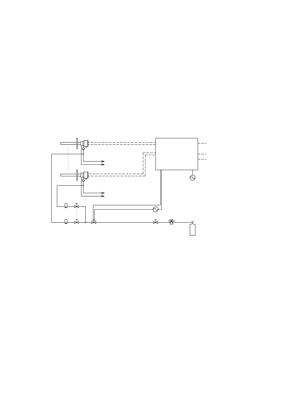
Piping to Introduce Purge Gas When a Process Gas Alarm Occurs
When a process gas alarm (an input contact signal of unburnt gas detection) occurs, the
averaging converter will cut off the power supply to the heater of the detector, and at the
same time it will send a contact output to activate a solenoid valve for introducing a
purge gas to the detector.
In addition to the system configuration shown in Figure 4.1, a purge gas cylinder and a
pressure reducing valve, and where necessary, a stop valve, a flowmeter, and a needle
valve are required. Also, a check valve should be installed on the calibration gas inlet of
the detector. A typical piping diagram for purging is shown in Figure 4.9.
It is recommended that each instrument be installed to allow for minimum piping
between the ZA8F Flow Setting Unit and the detector and between the solenoid valve
for introducing the purge gas and the detector.
Check valve
Check valve
To ZA8F
Calibration gas line
Reference gas line
To ZA8F
Averaging Converter (AV550G)
Heater
Signal
Contact output
purging gas cylinder
Flowmeter
Pressure regulator
Needlu valve
Reference gas line
Calibration gas line
Solenoid valve
Detector
Power supply
Contact input
Contact output
Analog outputs:
(Averaged and individual outputs)
Stop valve
Figure 4.9 Typical Piping for Purging