Yokogawa Multi Channel Oxygen Analyzer System ZR22/AV550G User Manual
Page 93
IM 11M12D01-01E
5-13
5. Wiring
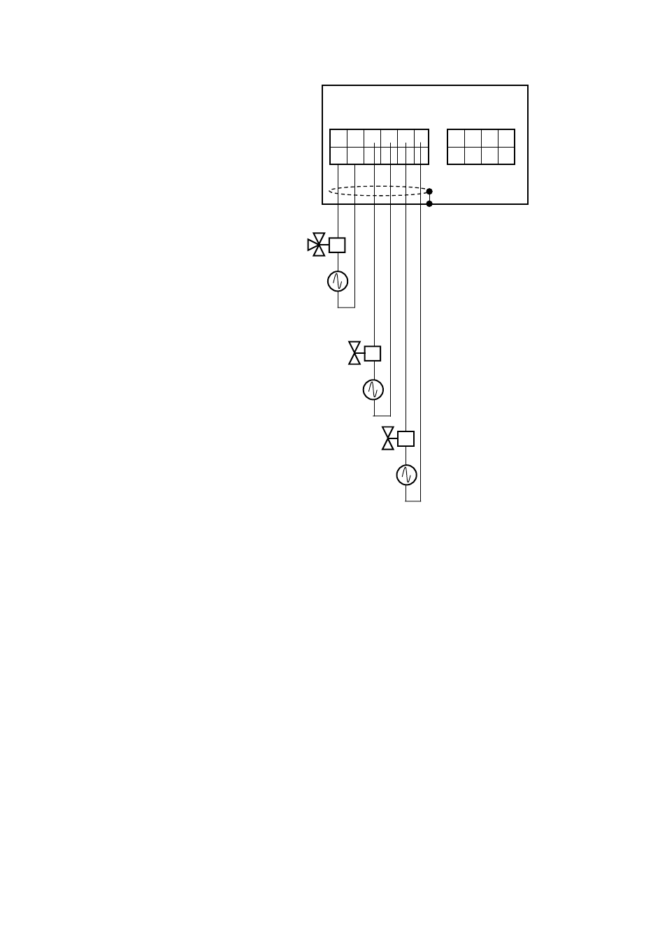
26 27 28 29
69 70 71 72
44 45 46 47 48 49
89 90 91 92
Averaging Converter
Shield
Basic Power Unit
Expansion Power Unit
Solenoid Valve for Switching
Zero/Span Cal Gases
Power Supply to Solenoid Valve
Solenoid Valve for Cal Gas to Detector #1
Power Supply to Solenoid Valve
Solenoid Valve for Cal Gas to Detector #2
Power Supply to Solenoid Valve
: If optional 24 V outputs are specified for solenoid valves (Option Code "/24"),
no external power supply for solenoid valves is required. The solenoid valves
are powered from the AV550G Averaging Converter. Never connect external
power sources in the wiring for solenoid valves.
ء
ء
ء
ء
5.2.9
Wiring for Individual/Common Error Contact Outputs and Common Contact
Outputs
The averaging converter has the following contact outputs.
(1) Common function-specific contact outputs (DO1 to DO4): User specified functions
can be assigned.
(2) Common error contact output (DO5): Activated when any error occurs.
(3) Individual error contact outputs (DO-CH1 to DO-CH8): Channel-specific contacts.
One output is provided per channel.
For details on errors, refer to Section 12.1, "Display and Remedies When Error Occur."
All contact outputs are Form C (transfer contact) and consist of 3 terminals of COM,
NC, and NO. All contacts are voltage free, dry contacts (mechanical relay contact
outputs). The contact rating is 250 VAC, 3A or 30 VDC, 3A.
The individual and common error contacts are set to normally energized and cannot be
changed. The "NC" and "NO" indications on the terminal show energized states. States
of common contacts 1 to 4 are user selectable: normally energized or normally
deenergized. The "NC" and "NO" indications on the terminal show deenergized states.