2 installation of the detector (model zr22g-015), 1 installation location, 5 pipinf for blowback – Yokogawa Multi Channel Oxygen Analyzer System ZR22/AV550G User Manual
Page 72
IM 11M12D01-01E
4-6
4.1.5
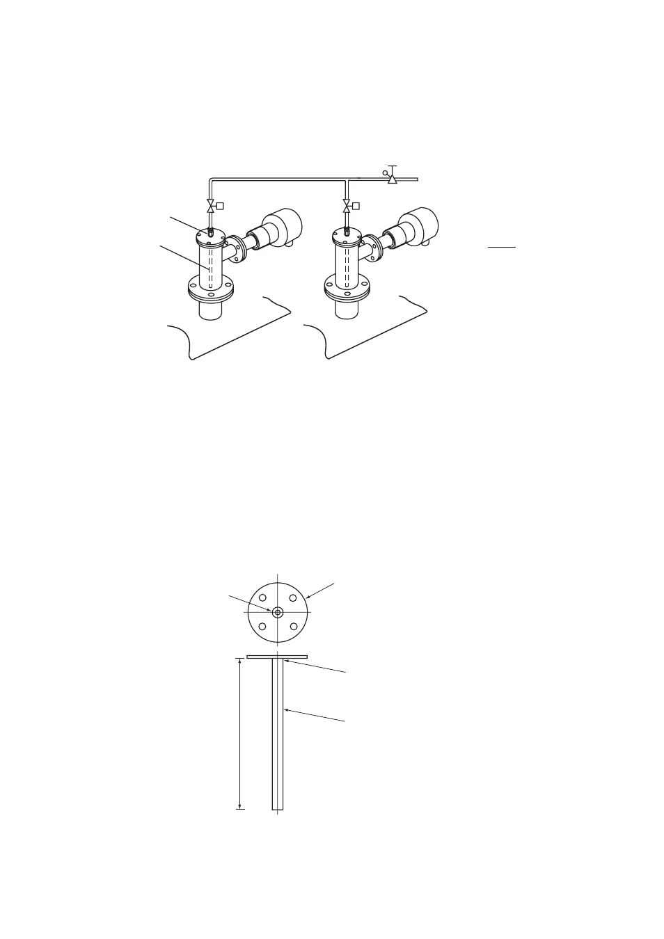
Pipinf for Blowback
This piping is required when the blow back function is carried out. The piping described
below provides automatic blow back operation when the “ blow back start “ command is
entered to the converter.
Pipe coupling
Blow pipe
Blowback air
Regulator valve
F4302.EPS
Solenoid valve
Solenoid valve
If blowback is done under control of a
contact output from the averaging
converter, a hold is placed on analog
output signals from all detector while
blowback is in progress.
See Section 10.5 for details on the
blowback function. Wiring for solenoid
valves is described in Section 5.3.
Note
Figure 4.6 Blowback Piping
The following parts are required for blow back piping.
• Blow pipe (to be prepared as illustrated in Figure 4.7.)
• Two-way solenoid valve: “ Open “ when electric current is on. (Found on the open
market)
• Air set (recommended by YOKOGAWA, G7011XF / E7040EL or G7004XF / K9473XG)
temperature probe adapter.
Approximately
200
Rc1/4
Blind flange of the adapter for
high temperature probe
Welded
8 (O.D.) by 6 (I.D.) Stainless steel pipe
F4.11E.EPS
Unit : mm
Figure 4.7 Blow pipe Construction