10 wiring for contact inputs – Yokogawa Multi Channel Oxygen Analyzer System ZR22/AV550G User Manual
Page 95
IM 11M12D01-01E
5-15
5. Wiring
5.2.10
Wiring for Contact Inputs
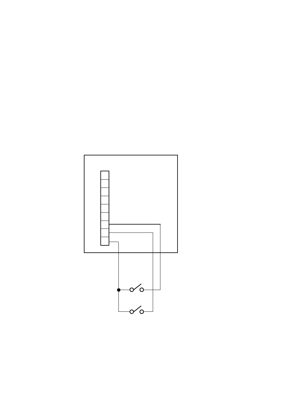
The averaging converter receives contact inputs to perform the specified functions.
Follow the instructions below to run the wiring for contact inputs.
Use 2-core or 3-core PVC insulated PVC sheathed control cable for this wiring. The
number of cores is determined by the number of contacts to be used. There is no need to
use shielded cables. If a cable gland is not installed on the wiring hole of the averaging
converter, use a wire with an outside diameter of 17 mm or smaller. If installed, use a
wire with an outside diameter of 6 to 12 mm. Like the signal wiring to detectors, the
shields should be connected to cable shield ground terminals on the case of the
averaging converter.
Contact inputs should be voltage free. The open/closed state of the contact is determined
by the resistance from the averaging converter side. Note that the resistance should
include the wiring resistance.
Closed contact: 200
⍀ or less
Open contact: 100 k
⍀ or more
7
8
9
Averaging Converter
Control Card
Contact Input 1
Contact Input 2
Figure 5.14 Wiring for Contact Inputs