Warning – Yokogawa Multi Channel Oxygen Analyzer System ZR22/AV550G User Manual
Page 88
IM 11M12D01-01E
5-8
5.2.3
Power and Ground Wiring
Connect the power wiring to the L and N terminals in the averaging converter. Use
wires with a size of 2 mm2 (14 AWG) or larger. If a cable gland is not installed on the
wiring hole of the averaging converter, use a wire with an outside diameter of 17 mm or
smaller. If installed, use a wire with an outside diameter of 6 to 12 mm. A lock washer
must be installed.
Connect the ground wiring to the protective ground terminal in the averaging converter
or the external ground terminal on the side of the case. Run the ground wiring so the
ground resistance is 100
Ω
or less (equivalent to Class D grounding).
Make sure that the jumper plate is connected between the G terminal and the protective
ground terminal.
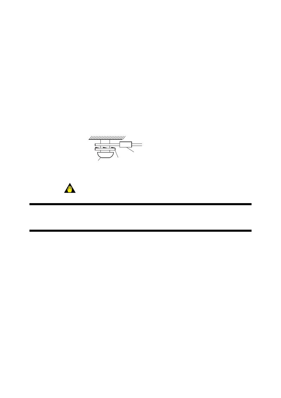
Grounding to the ground terminal
on the Averaging converter case
Converter Case
FG Terminal
Lock Washer
Crimp Terminal
Figure 5.6 Grounding to the Ground Terminal
WARNING
Operating the instrument with the jumper plate disconnected may result in poor
resistance to noise.
5.2.4
Power Wiring to Detector Heaters
This wiring provides electric power from the averaging converter to the heater for
heating the sensor in a detector. Use 2-core shielded PVC insulated PVC sheathed
control cables. The wire size should be 1.25 mm2 (16 AWG) or larger and the conductor
two-way resistance should be 10
Ω
or less. If a cable gland is not installed on the wiring
hole of the averaging converter, use a wire with an outside diameter of 17 mm or
smaller. If installed, use a wire with an outside diameter of 6 to 12 mm. The shields
should be connected to cable shield ground terminals on the case of the averaging
converter.