6 air set, 3 installation of the averaging converter – Yokogawa Multi Channel Oxygen Analyzer System ZR22/AV550G User Manual
Page 75
IM 11M12D01-01E
4-9
4. Piping
4.2
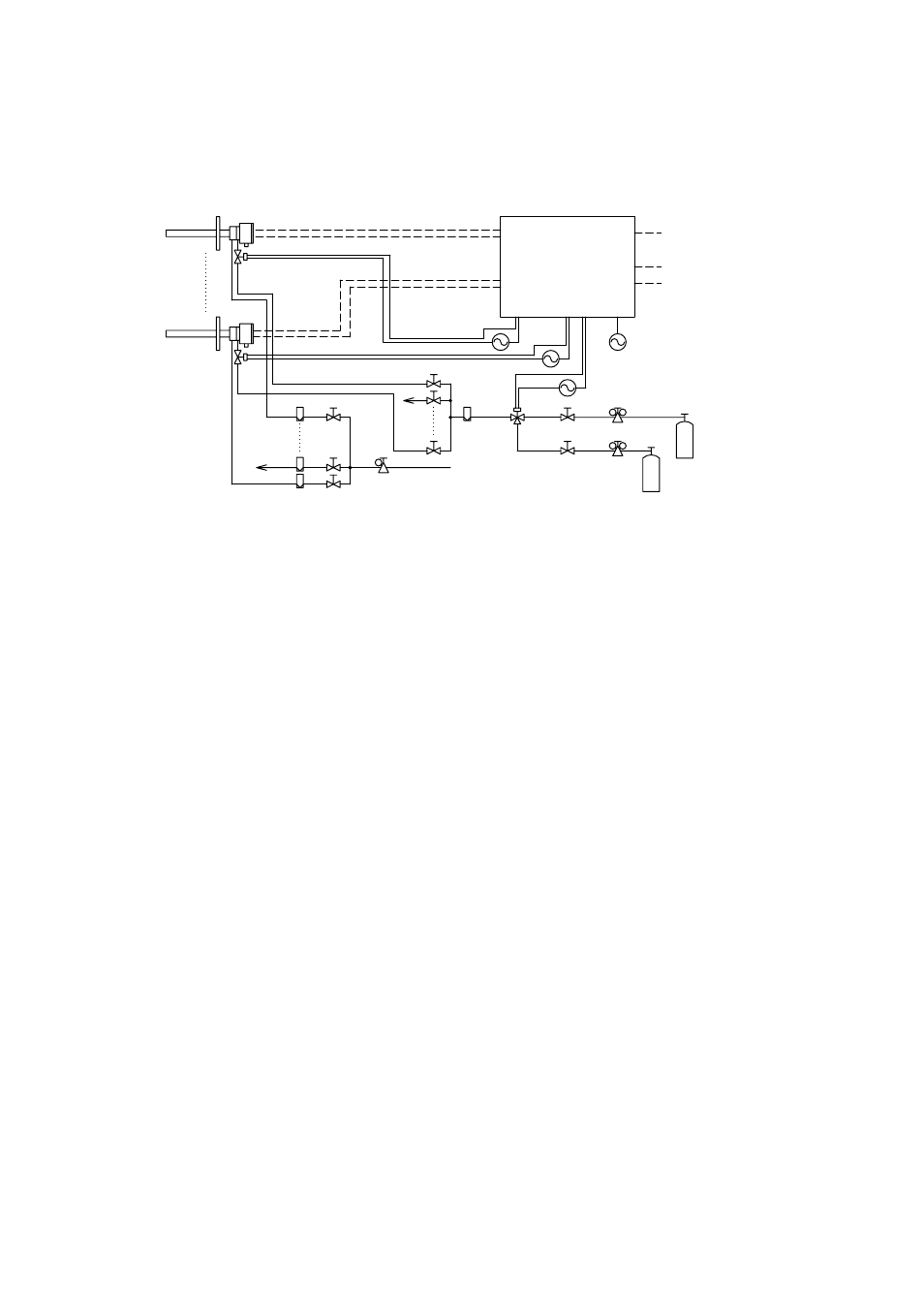
Piping for a System to Perform Automatic Calibration
The piping for a system to perform automatic calibration is shown in Figure 4.10.
Averaging Converter (AV550G)
Heater
Signal
Calibration contact outputs
Span gas cylinder
(Instrument air)
Zero gas cylinder
Flowmeter
Solenoid valve
Needle valve
Air set
Pressure regulator
Needle valve
Flowmeter
Reference gas
line
Calibration gas line
Solenoid valve
Detector
Power supply
Instrument air
Contact input
Contact output
Analog outputs:
Averaged and individual outputs
Stop valve
Figure 4.10 Typical Piping for a System to perform Automatic Calibration
The following outlines some points to note regarding the piping for this system.
• Install a solenoid valve through a nipple on the calibration gas inlet of the detector.
Note: The solenoid valve should be connected directly to the detector. If any piping is
present between the detector and the solenoid valve, condensation may develop
in the pipe, causing damage to the detector by rapid cooling when the
calibration gas is introduced.
• When a high temperature detector is used and the pressure of a sample gas is negative,
connect an auxiliary ejector on the sample gas outlet of the high temperature probe
adapter. (See Figure 4.3 in Subsection 4.1.4.)
• When a high temperature detector is used and the pressure of a sample gas is 0.49 Pa
or higher, it is recommended that a throttle (e.g., needle valve) be installed on the
sample gas outlet of the high temperature probe adapter. (See Figure 4.4 in Subsection
4.1.4.)
Note: This is to lower the temperature of a sample gas below 700
ЊC. When both
the temperature and the pressure of a sample gas are high, the temperature of
the sample gas may not fall below 700
ЊC before the gas reaches the detector.
On the other hand, the temperature of a sample gas may drop too much and thus
condensation develops in the high temperature probe ejector. During wintertime,
it is recommended that the probe adapter be protected with an insulating
material to prevent condensation.
Note: If optional 24 V outputs are specified for solenoid valves (Option Code "/24"),
no external power supply for solenoid valve is required. The solenoid valves
are powered from the AV550G Averaging Converter. Never connect external
power sources in the wiring for solenoid valves.
• When a high temperature detector is used and blowback is required to eliminate dust
accumulating in the probe of the high temperature probe adapter, air supply piping for
purging should be installed.
Note: If a sample gas contains much dust (e.g., in recovery boilers or cement kilns),
the probe is more likely to become clogged. To eliminate this dust accumulation
using air pressure, piping is generally installed from an air source only when
cleaning is performed. Some cases, however, may need a permanent installation
of the blowback piping. See Subsection 4.1.5 for the installation of blowback
piping.