5 piping for blowback, 2 preparation for wiring to detectors, Figure 5.4 detector terminals – Yokogawa Multi Channel Oxygen Analyzer System ZR22/AV550G User Manual
Page 86
IM 11M12D01-01E
5-6
5.2
Wiring for the Averaging Converter and Peripheral
Devices
5.2.1
Preparation for Wiring to the Averaging Converter
Follow the instructions below when connecting cables to the averaging converter.
(1) The terminal screws on the control and channel cards are M3.5, and all the other
terminal screws are M4. Each wire should be terminated with a crimp terminal
appropriate to the screw.
(2) If a silicone rubber insulated glass fiber braided wire is used for wiring to the
detector, run the wiring through a terminal box. It is recommended that a cable
such as a PVC insulated PVC sheathed control cable be used between the terminal
box and the averaging converter. This is to prevent moisture or corrosive gases
from entering into the averaging converter and to ensure the grounding of the
detector.
5.2.2
Preparation for Wiring to Detectors
Follow the instructions below when connecting cables to detectors.
(1) Install a conduit or cable gland appropriate to the specified screw size to the cable
inlet of a detector. Allow for the sufficient length of a cable in case that the detector
needs to be removed for maintenance.
(2) If the ambient temperature around the wiring lines exceeds 80˚C, a flexible metal
conduit tube must be used. If an unshielded 600 V silicon rubber insulated glass fiber
braided wire, route the wiring so that the wire cannot pick up external noise.
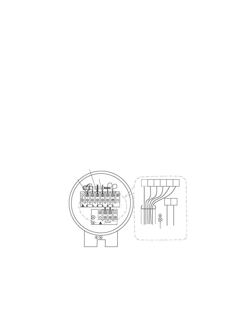
(3) Figure 5.4 shows the layout of the detector terminals.
CELL
ϩ
TC
ϩ
(with Si TUBE)
TC
Ϫ
TC
CELL
CJ
1
2 3
4 5
6
8
7
H T R
CELL
(+)
CELL
(-)
TC
(+)
TC
(-)
CJ
(+)
CJ
(-)
HTR
HTR
To Converter,
or
Terninal Box
To Converter,
or
Terminal Box
To Ground
Figure 5.4 Detector Terminals