10 wiring for contact inputs, 2 av550g averaging converter, 1 components and function – Yokogawa Multi Channel Oxygen Analyzer System ZR22/AV550G User Manual
Page 113: 2 touchpanel switch operations, 1 panels and switches, 4 setting detector model, Detector, Channel card power
IM 11M12D01-01E
7-3
7. Startup
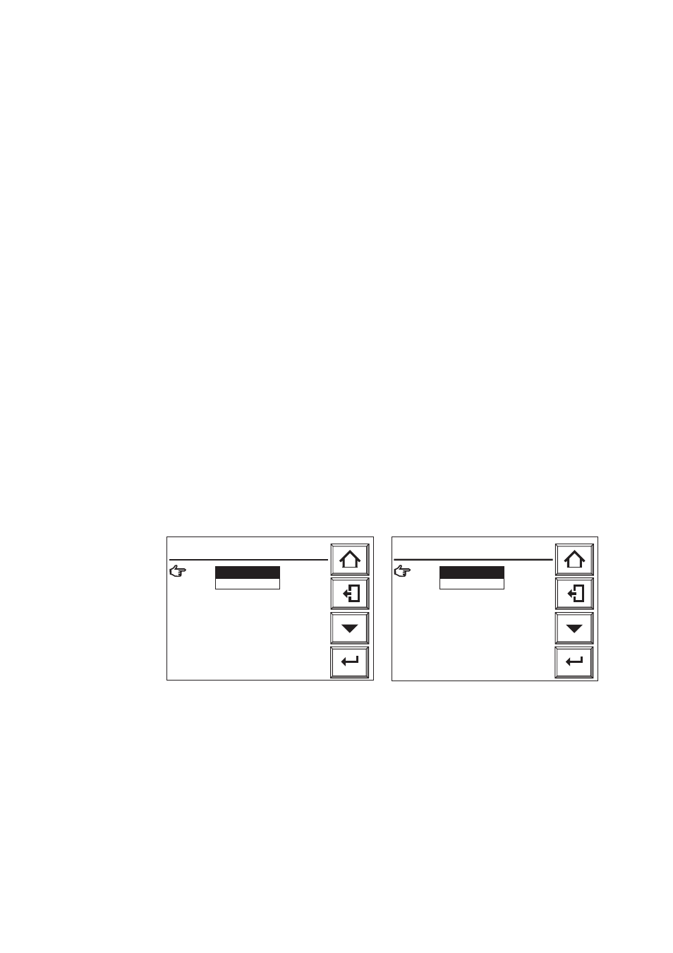
7.4 Setting Detector model
The default detector model set before shipment from the factory is ZR22G. If you plan
to use the "ZO21D
*
" then before starting warmup you need to change the default
setting. If you do not change the setting before starting warmup then detector tempera-
ture control will not work properly and serious damage to the detector may result.
There are two ways of changing this setting before warmup, as follows:
[ How to use Channel-card "Hot Swap" feature]
This converter allows you to toggle the power supply of individual channel cards OFF/
ON while power to the converter is applied. This method also allows you change the
detector model settings without detector warm up.
1) Touch the Setup key, and the [Execution/Setup] display appears.
2) Move the arrow pointer key to [Maintenance] and touch the Enter key.
3) On the Maintenance display, select [Channel card power] and touch the Enter key. A
display like that shown in Fig. 7.3 appears.
4) On the Channel Card Power display, select the channel no. of a channel connected to
a ZO21D
*
then touch the Enter key.
5) A [Disable/Enable] selection window is displayed. Select [Disable] and touch Enter.
Confirm that the status display lamp of the corresponding channel turns off.
6) Repeat the above procedure for each channel connected to a ZO21D* and disable
power.
7) Touch the Home key to return to the [Run / Set Data] display.
8) Select [Commissioning] --> [Basic setup] --> [Detector], then the Detector Selection
display appears.
9) Select each channel to be connected to a ZO21D* and change the ZR22G default to
ZO21D.
10) After changing the settings for all channels to be connected to ZO21D* detectors,
turn off converter power.
᭜
Ch2 : ZO21D
᭜
Ch3 : ZR22G
᭜
Ch4 : ZO21D
᭜
Ch5 : ZR22G
᭜
Ch6 : ZO21D
᭜
Ch7 : ZR22G
᭜
Ch8 : ZO21D
Detector
Enter
F7.2E.EPS
Ch1 : ZR22G
ZR22G
Enter
Ch1 : ZR22G
᭜
Ch2 : Enable
᭜
Ch3 : Enable
᭜
Ch4 : Enable
᭜
Ch5 : Enable
᭜
Ch6 : Enable
᭜
Ch7 : Enable
᭜
Ch8 : Enable
F7.3E.EPS
Disable
Channel card power
Fig. 7.2 Detector Selection Fig.7.3 Channel Card Power Setting
.