Function block descriptions, Action function, Alarm function – Watlow EZ-ZONE RME User Manual
Page 94
Watlow EZ-ZONE
®
RME Module
•
91
•
Chapter 6 Features
Function Block Descriptions
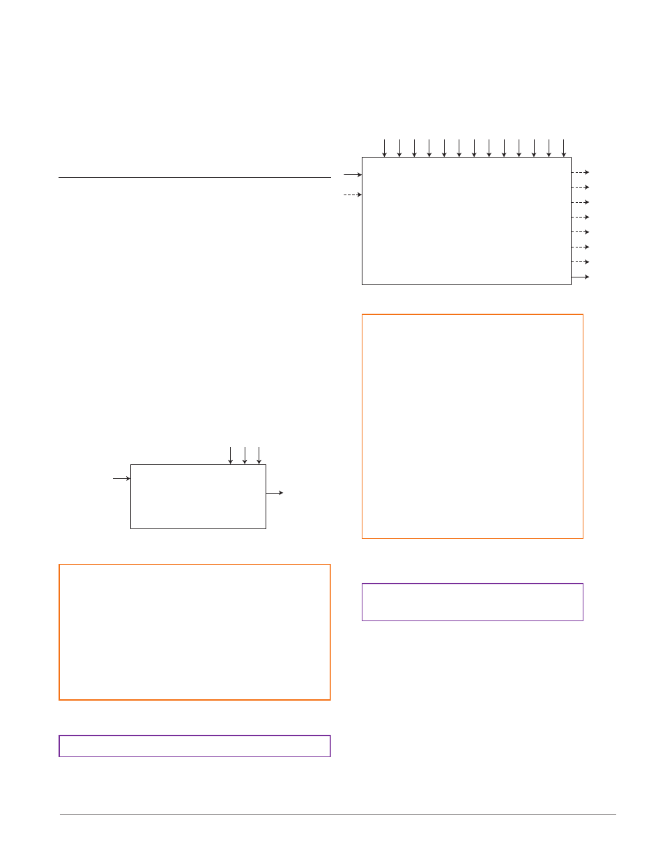
Each of the next several pages graphically shows each of
the RME function blocks. Note that as you view each you
will find text that is black and text that appears gray. The
gray text represents inputs that are not currently available
based on the functions defined use (red text). For instance,
when the defined use of the Alarm function is set to Off,
all parameters will appear gray. Ranges specified are in
units or degrees F, if expressed in degrees C, the range will
be smaller.
Action Function
The Action Function will cause the action selected
to occur when Source Function A = ON and Active
Level = High. The active level specifies when the ac-
tion occurs. A digital value that is high causes the
action function when Active Level = High. A digital
value that is low causes the action function when Ac-
tive Level = Low. Based on a given input (Digital I/O,
Event output, Logic function, etc), the Action func-
tion can cause other functions to occur. To name a
few, starting and stopping a profile, silencing alarms,
turn control loops off and placing alarms in non-
alarm state.
Note:
Note: Action Function selection is module type and
part number dependant.
[``Fi]
Function Instance : 0 to 8
[SFn;A]
Source Function A : None, Alarm, Compare, Counter, Digital
I/O, Profile Event Out A to H, Function Key, Limit, Logic,
Timer, Variable
[`Leu]
Active Level : High, Low
[``Fn]
Action Function : None, User Set Restore, Alarm, Silence
Alarms, Control Loops Off and Alarms to Non-alarm State,
Force Alarm to Occur
[`Si;A]
Source Instance A : 1 to 250
[`S2;A]
Source Zone A : 0 to 16
Action
Overview
Instances - 8 per RME
Active Level
Function Instance
Action Function
Event Status
Source Function A
Source Instance A
[`E;iS]
Event Status : On, Off
[`ACt]
Action Menu
[`SEt]
Setup Page
[`ACt]
Action Menu
[oPEr]
Operation Page
Alarm Function
The Alarm function will cause the output to change
states when Alarm Source exceeds Alarm Set Points.
Alarm
Overview
Instances - 8 per RME
Alarm Latching
Alarm Blocking
Alarm Silencing
Alarm Hysteresi
s
Alarm Clear Reques
t
Alarm Silence Reques
t
Alarm
Type
Alarm Logi
c
Alarm Side
s
Alarm Displa
y
Alarm Delay
Time
Alarm Low Set
Point
Alarm High Set
Point
[`Sr;A]
Alarm Source : Analog Input, Current, Power,
Linearization, Math, Process Value, Variable
[`S2;A]
Alarm Source Zone : 0 to 16
[`iS;A]
Alarm Source Instance : 1 to 250
[`A;ty]
Alarm Type : Off, Process
[`A;Lg]
Alarm Logic : Close on Alarm, Open on Alarm
[`A;Si]
Alarm Silencing : Off, On
[`A;LA]
Alarm Latching : Non-Latching, Latching
[`A;dL]
Alarm Delay Time : 0 to 9,999 seconds
Alarm Clear Request : Ignore, Clear
Alarm Silence Request : Ignore, Silence
[`A;hi]
Alarm High Set Point : -1,999.000 to 9,999.000
[`A;hi]
Alarm High Set Point : -1,999.000 to 9,999.000
[`A;hy]
Alarm Hysteresis : 0.001 to 9,999.000
[`A;bL]
Alarm Blocking : Off, Startup, Set Point, Both
[`A;Sd]
Alarm Sides : Both, High, Low
[A;dSP]
Alarm Display : Off, On
[`A;Lo]
Alarm Low Set Point : -1,999.000 to 9,999.000
[`A;Lo]
Alarm Low Set Point : -1,999.000 to 9,999.000
Alarm Clearable : No, Yes
Alarm Latched : No, Yes
Alarm Silenced : No, Yes
Output Value : On, Off
Error : None, Open, Shorted, Measurement Error, Bad
Cal Data, Ambient Error, Fail, Not Sourced
Alarm Working Set Point : -1,999.000 to 9,999.000
Alarm Working Process Value : -1,999.000 to 9,999.000
Output Value
Alarm Clearable
Alarm Working Process Value
Alarm Working Set Point
Alarm Latched
Alarm Silenced
Alarm State
[ALM]
Alarm Menu
[`SEt]
Setup Page
[ALM]
Alarm Menu
[oPEr]
Operation Page
Error
Alarm State : Startup, None, Blocked, Alarm Low,
Alarm High, Error
Alarm Source
Alarm Source Instance
Alarm Source Zone
Alarm Source Error