Saving and restoring user settings, Inputs, Outputs – Watlow EZ-ZONE RME User Manual
Page 85: Saving and restoring user settings inputs outputs, Variable time base, Ten point linearization
Watlow EZ-ZONE
®
RME Module
•
82
•
Chapter 6 Features
Saving and Restoring User Settings
Recording setup and operations parameter settings
for future reference is very important. If you uninten-
tionally change these, you will need to program the
correct settings back into the controller to return the
equipment to operational condition.
After you program the controller and verify prop-
er operation, use User Settings Save [USr;S] (Setup
Page, Global Menu) to save the settings into either of
two files in a special section of memory.
Note:
Starting with firmware release 6, there is only one
user set.
If the settings in the controller are altered and you
want to return the controller to the saved values, use
User Settings Restore [USr;r] (Setup Page, Global
Menu) to recall the previously saved settings.
A digital input or the Function Key can also be
configured to restore parameters.
CAUTION:
If a Digital Input or Function Key is programmed for
User Setting Restore, the operator may select Fac-
tory Restore and the Digital Input or Function Key
may no longer be programmed for User Setting Re-
store.
Note:
Only perform the above procedure when you are sure
that all the correct settings are programmed into the
controller. Saving the settings overwrites any previ-
ously saved collection of settings. Be sure to document
all the controller settings.
Inputs
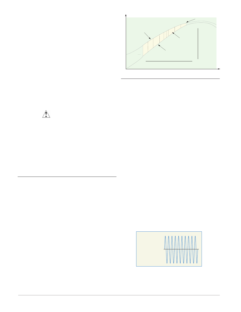
Ten Point Linearization
The linearization function allows a user to re-linear-
ize a value read from an analog source. The function
selections are Off, Interpolated and Stepped. When
set to Off the output will match the Source A value
plus offset. There are 10 data points used to compen-
sate for differences between the source value read
(input point) and the desired value (output point).
Multiple data points enable compensation for non-
linear differences between the sensor readings and
target process values over the thermal or process sys-
tem operating range. Sensor reading differences can
be caused by sensor placement, tolerances, an inaccu-
rate sensor or lead resistance.
The user specifies the unit of measurement and
then each data point by entering an input point value
and a corresponding output point value. Each data
point must be incrementally higher than the previous
point. The linearization function will interpolate data
points linearly in between specified data points.
2
3
4
5 6
7
8
9
Reading from Sensor
without Linearization
(Actual Value)
Input Point 1
Output Point 1
Input Point 10
Output Point 10
Offset Zone
Reading from Sensor
with Linearization
(Displayed Value)
No Offset
T
emperature
Time
Outputs
Variable Time Base
Variable time base is the preferred method for con-
trolling a resistive load, providing a very short time
base for longer heater life. Unlike phase-angle firing,
variable-time-base switching does not limit the cur-
rent and voltage applied to the heater.
With variable time base outputs, the PID algo-
rithm calculates an output between 0 and 100%, but
the output is distributed in groupings of three ac
line cycles. For each group of three ac line cycles, the
controller decides whether the power should be on or
off. There is no fixed cycle time since the decision is
made for each group of cycles. When used in conjunc-
tion with a zero cross (burst fire) device, such as a
solid-state power controller, switching is done only at
the zero cross of the ac line, which helps reduce elec-
trical noise (RFI).
Variable time base should be used with solid-state
power controllers, such as a solid-state relay (SSR)
or silicon controlled rectifier (SCR) power controller.
Do not use a variable time base output for control-
ling electromechanical relays, mercury displacement
relays, inductive loads or heaters with unusual resis-
tance characteristics.
The combination of variable time base output and
a solid-state relay can inexpensively approach the ef-
fect of analog, phase-angle fired control.
Select the AC Line Frequency [AC;LF] (Setup Page,
Global Menu), 50 or 60 Hz.
100 percent output
10 ON, 0 OFF