1 to 24), Switched dc to din-a-mite, Digital output – Watlow EZ-ZONE RME User Manual
Page 25: Wiring example, Wiring example - open collector
Warning:
ç
Use National Electric (NEC) or other
country-specific standard wiring and
safety practices when wiring and
connecting this controller to a power
source and to electrical sensors or pe-
ripheral devices. Failure to do so may
result in damage to equipment and
property, and/or injury or loss of life.
Note:
Maximum wire size termination
and torque rating:
• 0.0507 to 3.30 mm
2
(30 to 12
AWG) single-wire termination
or two 1.31 mm
2
(16 AWG)
• 0.8 Nm (7.0 in-lb.) torque
Note:
Adjacent terminals may be la-
beled differently, depending on
the model number.
Note:
To prevent damage to the con-
troller, do not connect wires to
unused terminals.
Note:
Maintain electrical isolation
between digital input-outputs,
switched dc/open collector out-
puts and process outputs to
prevent ground loops.
Note:
If the last two digits of the part
number are "12", this Equip-
ment is suitable for use in
CLASS I, DIVISION 2, Groups
A, B, C and D or Non-Hazard-
ous locations only. Temperature
Code T4
Warning:
ç
Explosion Hazard – Substitution of
component may impair suitability for
CLASS I, DIVISION 2.
Warning:
ç
Explosion Hazard - Do not disconnect
while the circuit is live or unless the
area is known to be free of ignitable
concentrations of flammable sub-
stances.
Watlow EZ-ZONE
®
RME Module
•
22
•
Chapter 2 Install and Wire
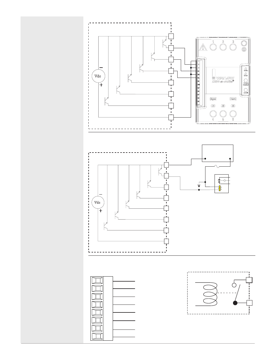
Digital Output (
1 to 24)
Wiring Example -
Switched DC to DIN-A-MITE
®
Vdc
Collector Outputs
Internal Circuitry
Internal Supply
+
+
+
-
-
-
DC90-60C0-0000
Htr 3
Htr 2
Htr 1
B_
D_
Z_
D_
D_
D_
D_
D_
Common
Digital Output (
1 to 24)
Wiring Example - Open Collector
Vdc
Collector Outputs
Internal Circuitry
Power Supply
5 to 32 Vdc
Relay
+
-
Common
Internal Supply
Diode
Fuse
An example fuse is
Bussmann AGC-1 1/2
B_
D_
D_
D_
D_
D_
D_
Z_
Quad Mechanical Relays, Form A Outputs 1-4, 7-10, 13-16
RME Part # Digit 5, 6, or 7 is J
normally open
common
L_
K_
L_
K_
L_
K_
L_
K_
Slot A, B, D
normally open
common
normally open
common
normally open
common
• 5 A at 240V (ac) or 30V
(dc) maximum resistive
load
• 20 mA at 24V minimum
load
• 125VA pilot duty at
120/240V (ac), 25 VA at
24V (ac)
• 100,000 cycles at rated
load
• output does not supply
power
• For use with ac or dc
• Not available in slot E
• See Quencharc note.
L_
K_
Quencharc Note:
Switching pilot duty inductive loads
(relay coils, solenoids, etc .) with the
mechanical relay, Solid-State relay or
open collector output options requires
use of an R .C . suppressor
.