Wiring – Watlow EZ-ZONE RME User Manual
Page 19
Watlow EZ-ZONE
®
RME Module
•
16
•
Chapter 2 Install and Wire
Wiring
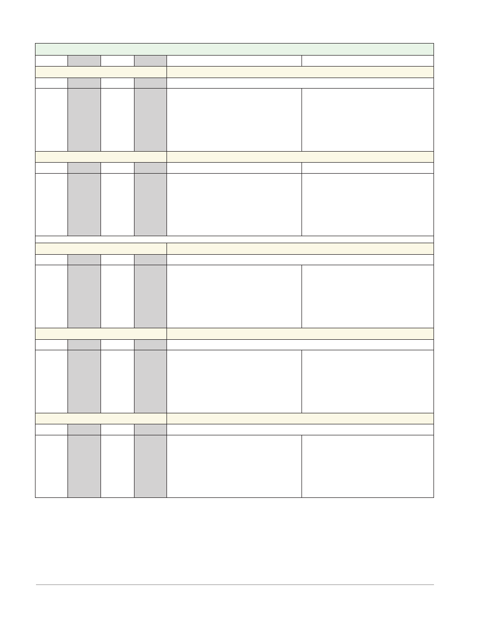
Expansion Module (RME x - x x x x - x x x x)
Slot A
Slot B
Slot D
Slot E
Terminal Function
Configuration
Inputs
Digital Inputs
1 - 6
7 - 12
13 - 18
19 - 24
B1
D1
D2
D3
D4
D5
D6
Z1
B7
D7
D8
D9
D10
D11
D12
Z7
B13
D13
D14
D15
D16
D17
D18
Z13
B19
D19
D20
D21
D22
D23
D24
Z19
Common
dc+ input
dc+ input
dc+ input
dc+ input
dc+ input
dc+ input
Internal Supply
6 Digital Inputs
Part # Digits 5, 6, 7, 8
Slot A: RME _ - [C] _ _ _ - _ _ _ _
Slot B: RME _ - _ [C] _ _ - _ _ _ _
Slot D: RME _ - _ _ [C] _ - _ _ _ _
Slot E: RME _ - _ _ _ [C] - _ _ _ _
Current Transformer Inputs
- - -
- - -
- - -
13 - 16
- - -
- - -
- - -
- - -
- - -
- - -
- - -
- - -
- - -
- - -
- - -
- - -
- - -
- - -
- - -
- - -
- - -
- - -
- - -
- - -
- - -
- - -
- - -
- - -
T13
S13
T14
S14
T15
S15
T16
S16
mA ac
mA ac
mA ac
mA ac
mA ac
mA ac
mA ac
mA ac
Quad Current Transformers
Part # Digit 8
Slot E: RME _ - _ _ _ [T] - _ _ _ _
Outputs
Digital Outputs
1 - 6
7 - 12
13 - 18
19 - 24
B1
D1
D2
D3
D4
D5
D6
Z1
B7
D7
D8
D9
D10
D11
D12
Z7
B13
D13
D14
D15
D16
D17
D18
Z13
B19
D19
D20
D21
D22
D23
D24
Z19
common
open collector/ switched dc
open collector/ switched dc
open collector/ switched dc
open collector/ switched dc
open collector/ switched dc
open collector/ switched dc
internal supply
Digital Inputs
Part # Digits 5, 6, 7, 8
Slot A: RME _ - [C] _ _ _ - _ _ _ _
Slot B: RME _ - _ [C] _ _ - _ _ _ _
Slot D: RME _ - _ _ [C] _ - _ _ _ _
Slot E: RME _ - _ _ _ [C] - _ _ _ _
4, 2A Solid-State Relay (SSR) Outputs
1 - 4
7 - 10
13 - 16
19 - 22
L1
K1
L2
- - -
- - -
L3
K3
L4
L7
K7
L8
- - -
- - -
L9
K9
L10
L13
K13
L14
- - -
- - -
L15
K15
L16
L19
K19
L20
- - -
- - -
L21
K21
L22
normally open
common
normally open
not used
not used
normally open
common
normally open
2A SSR Outputs
Part # Digits 5, 6, 7, 8
Slot A: RME _ - [L] _ _ _ - _ _ _ _
Slot B: RME _ - _ [L] _ _ - _ _ _ _
Slot D: RME _ - _ _ [L] _ - _ _ _ _
Slot E: RME _ - _ _ _ [L] - _ _ _ _
Tri-State Process/Retransmit Outputs
1 - 3
7 - 9
13 - 15
19 - 21
F1
H1
- - -
F2
H2
- - -
F3
H3
F7
H7
- - -
F8
H8
- - -
F9
H9
F13
H13
- - -
F14
H14
- - -
F15
H15
F19
H19
- - -
F20
H20
- - -
F21
H21
voltage or current -
voltage + or current +
not used
voltage or current -
voltage + or current +
not used
voltage or current -
voltage + or current +
Tri-Process Outputs
Part # Digits 5, 6, 7, 8
Slot A: RME _ - [F] _ _ _ - _ _ _ _
Slot B: RME _ - _ [F] _ _ - _ _ _ _
Slot D: RME _ - _ _ [F] _ - _ _ _ _
Slot E: RME _ - _ _ _ [F] - _ _ _ _