Alarm blocking, Programming the ez key/s, Using lockout to hide pages and menus – Watlow EZ-ZONE RME User Manual
Page 88
Watlow EZ-ZONE
®
RME Module
•
85
•
Chapter 6 Features
Alarm Blocking
Alarm blocking allows a system to warm up after
it has been started up. With alarm blocking on, an
alarm is not triggered when the process tempera-
ture is initially lower than the alarm low set point
or higher than the alarm high set point. The process
temperature has to enter the normal operating range
beyond the hysteresis zone to activate the alarm
function.
If the RME module has an output that is function-
ing as a deviation alarm, the alarm is blocked when
the set point is changed, until the process value re-
enters the normal operating range.
Turn Alarm Blocking [`A;bL] on or off via the
Setup Page, Alarm Menu.
Programming the EZ Key/s
If using an RUI the EZ Key can be configured either
in the Setup Menu or with EZ-ZONE configurator
software, using a personal computer.
The following examples show how to program the
EZ Key to start and stop a profile.
1. To go to the Setup Page from the Home Page,
press both the Up ¿ and Down ¯ keys for six sec-
onds. [``Ai] will appear in the upper display and
[`Set]
will appear in the lower display.
2. Press the Up Key ¿ until [`Fun] appears in the
upper display and [`SEt] will appear in the lower
display.
3. Press the Advance Key
‰
until Digital Input Level
[`leu]
appears in the lower display. Use an ar-
row key to specify the state of the key (high or low)
when the controller is powered up. Functions will
toggle with each press of the EZ Key, such as Pro-
file Start/Stop.
4. Press the Advance Key
‰
. The lower display will
show Digital Function [``Fn]. Press the Up ¿ or
Down ¯ key to scroll through the functions that
can be assigned to the EZ Key
When Profile Start/Stop [P;StS] appears in the
upper display and [``Fn] appears in the lower
display, press the Advance Key
‰
once to select
that function and move to the Function Instance
[``Fi]
parameter.
5. Press the Up ¿ or Down ¯ key to scroll to the
profile that you want the EZ Key to control.
6. The instance tells the controller which of the
numbered functions should be acted upon. For
profiles, there are 25 instances. Press the Infin-
ity Key ˆ once to return to the submenu, twice to
return to the main menu or three times to return
to the Home Page.
Using Lockout to Hide Pages and Menus
If unintentional changes to parameter settings might
raise safety concerns or lead to downtime, your can
use the lockout feature to make them more secure.
These settings will affect any access using Standard
Bus, including the RUI. This does not affect field pro-
tocol access.
Each of the menus in the Factory Page and each
of the pages, except the Factory Page, has a security
level assigned to it. You can change the read and
write access to these menus and pages by using the
parameters in the Lockout Menu (Factory Page).
Lockout Menu
There are five parameters in the Lockout Menu (Fac-
tory Page):
• Lock Operations Page [LoC;o] sets the security
level for the Operations Page. (default: 2)
Note:
The Home and Setup Page lockout levels are fixed
and cannot be changed.
• Lock Profiling Page [LoC;P] sets the security level
for the Profiling Page. (default: 3)
• Password Security Enable [pas;e] will turn on or
off the Password security feature. (default: off)
• Read Lockout Security [rLoC] determines which
pages can be accessed. The user can access the se-
lected level and all lower levels. (default: 5)
• Set Lockout Security [SLoC] determines which
parameters within accessible pages can be written
to. The user can write to the selected level and all
lower levels. (default: 5)
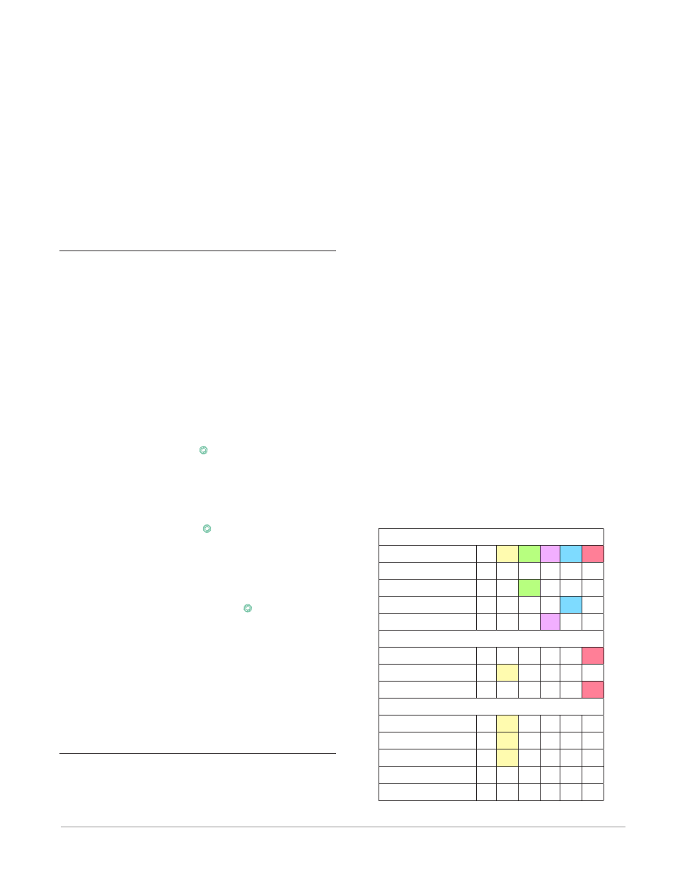
The table that follows represents the various levels
of lockout for the Set Lockout Security prompt and
the Read Lockout Security prompt. The Set Lockout
has 6 levels (0-5) of security where the Read Lockout
has 5 (1-5). Therefore, level "0" applies to Set Lockout
only. "Y" equates to yes (can write/read) where "N"
equates to no (cannot write/read). The colored cells
simply differentiate one level from the next.
Lockout Security [SLoC] & [rloC]
Lockout Level
0
1
2
3
4
5
Home Page
Y Y
Y Y Y
Y
Operations Page
N N
Y Y Y
Y
Setup Page
N N N N Y
Y
Profile Page
N N N Y Y
Y
Factory Page
Custom Menu
N N N N N Y
Diagnostic Menu
N Y
Y Y Y
Y
Calibration Menu N N N N N Y
Lockout Menu
[LoC;O]
N Y
Y Y Y
Y
[ loC; p]
N Y
Y Y Y
Y
[ pas ; e]
N Y
Y Y Y
Y
[rloC]
Y Y
Y Y Y
Y
[sloC]
Y Y
Y Y Y
Y