Outputs, Actions, Inputs – Watlow EZ-ZONE RME User Manual
Page 10
Watlow EZ-ZONE
®
RME Module
•
7
•
Chapter 1 Overview
RMC module
- The logic block (within the RME module) is config-
ured as an OR function
- The RME output function is tied to the internal out-
put of the logical OR function
When either process alarm is true (analog input val-
ue is greater than the alarm high set point, the real-
world output connected to the RME will be driven on.
Control
Function
Analog
Input
Function
Output
Function
Alarm
Function
Output
Function
Logic
Function
*
* RMC module
*
* RMC module
* RMC module
*
* RME module
* RME module
* RME module
*
*
*
Outputs
Outputs can perform various functions or actions in
response to information provided by a function, such
as a digital output to turn a light on or off, unlocking
a door; or turning on a buzzer.
Assign a function to an output in the Output
Menu or Digital Output Menu of the Setup Page.
Then select which instance of that function will drive
the selected output. For example, you might assign
an output to respond to an internal output of a com-
pare function.
You can assign more than one output to respond
to a single instance of a function, e.g., alarm 2 could
be used to trigger a light connected to output 1 and a
siren connected to digital output 5.
Actions
Based on a given input (Digital I/O, Logic function,
etc..) the Action function can cause other functions to
occur. To name a few, silencing alarms, turn control
loops off and placing alarms in non-alarm state.
that instance alone that will be reset.
Note:
Alarms will reset automatically when the condition
that caused the alarm goes back to a non-alarm state
if the alarm latching prompt is set to non-latching
(Setup Page, Alarm Menu).
Keep in mind that a function is a user-programmed
internal process that does not execute any action
outside of the controller. To have any affect outside
of the controller, an output must be configured to re-
spond to a function.
Some functions have a hardware input for which
the source/s are preset and cannot be changed. As
an example, CT 1 source function comes not surpris-
ingly, from the CT attached to it. Most functions can
accept more than one input and it would not be un-
common to see the output of one function (internal)
serve as an input to another, as would be the case
with a compare function. The source parameters for
the first input to a function are called Source Func-
tion A, Source Instance A and Source Zone A and the
second input, Source Function B, Source Instance B
and Source Zone B and so on.
Inputs
The inputs provide the information that any given
programmed function can act upon. This information
may come from an operator pushing a button, or as
part of a more complex function it may represent one
of ten inputs used for the Linearization function.
Each digital input reads whether a device is active
or inactive. An RME module can be equipped with up
to 24 digital inputs, where the RM system can have
many more. Each digital I/O point must be config-
ured to function as an input or an output with the
direction parameter in the digital I/O Menu (Setup
Page).
Another concept that needs to be understood is
the difference between an input tied to a real-world
device such as a CT and one that is tied to an inter-
nal function.
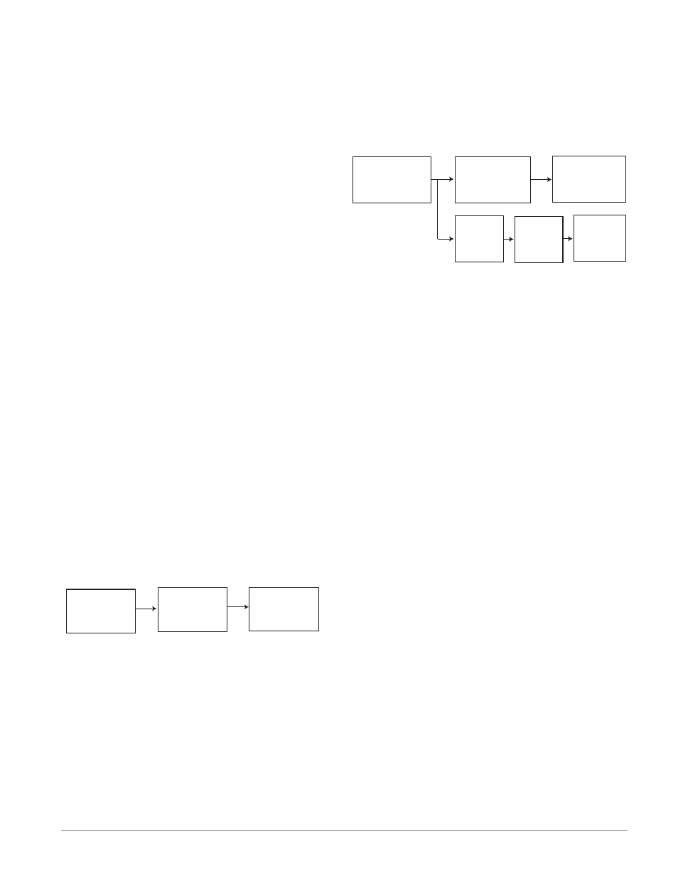
Alarm
Function
Current
Function
Output
Function
In the example above one can see the Current func-
tion on the left which is connected to a real-world
input device (CT) where on the far right the internal
output of the Alarm function is tied to the input of
the Output function where a real-world output device
is then driven such as a siren or a flashing light.
With a slight modification of the graphic above the
example below now ties the real-world analog inputs
from an RMC module directly to its PID control. The
RME module is using the same analog input to drive
an alarm function. For the sake of this example the
following is true:
- Within the RME two unique high process alarms
are configured for analog inputs 1 and 2 of the