Standard bus eia-485 communications, Watlow ez-zone, Rme module – Watlow EZ-ZONE RME User Manual
Page 28: Chapter 2 install and wire
Watlow EZ-ZONE
®
RME Module
•
25
•
Chapter 2 Install and Wire
Warning:
ç
Use National Electric (NEC) or other
country-specific standard wiring and
safety practices when wiring and
connecting this controller to a power
source and to electrical sensors or pe-
ripheral devices. Failure to do so may
result in damage to equipment and
property, and/or injury or loss of life.
Note:
Maximum wire size termination
and torque rating:
• 0.0507 to 3.30 mm
2
(30 to 12
AWG) single-wire termination
or two 1.31 mm
2
(16 AWG)
• 0.8 Nm (7.0 in-lb.) torque
Note:
Adjacent terminals may be la-
beled differently, depending on
the model number.
Note:
To prevent damage to the con-
troller, do not connect wires to
unused terminals.
Note:
Maintain electrical isolation
between digital input-outputs,
switched dc/open collector out-
puts and process outputs to
prevent ground loops.
Note:
If the last two digits of the part
number are "12", this equip-
ment is suitable for use in
CLASS I, DIVISION 2, Groups
A, B, C and D or Non-Hazard-
ous locations only. Temperature
Code T4
Warning:
ç
Explosion Hazard – Substitution of
component may impair suitability for
CLASS I, DIVISION 2.
Warning:
ç
Explosion Hazard - Do not disconnect
while the circuit is live or unless the
area is known to be free of ignitable
concentrations of flammable sub-
stances.
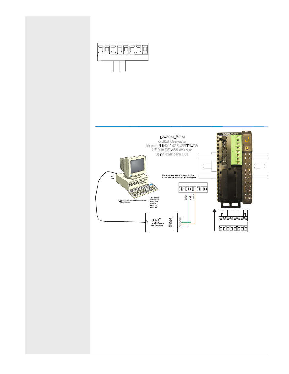
Standard Bus EIA-485 Communications
T-/R-
common
Slot C
T+/R+
98 99
CF CD CE
CZ CX CY
• Wire T-/R- to the A ter-
minal of the EIA-485
port.
• Wire T+/R+ to the B
terminal of the EIA-485
port.
• Wire common to the
common terminal of the
EIA-485 port.
• Do not route network
wires with power wires.
Connect network wires
in daisy-chain fashion
when connecting mul-
tiple devices in a net-
work.
• A 120 Ω termination re-
sistor may be required
across T+/R+ and T-/R-,
placed on the last con-
troller on the network.
• Do not connect more
than 16 EZ-ZONE RM
controllers on a net-
work.
• maximum network
length: 1,200 meters
(4,000 feet)
• 1/8th unit load on EIA-
485 bus
Slot C
98 99 CF CD CE CZ CX CY
98 99 CF CD CE CZ CX CY
Use twisted pair wires such as Cat 5 cabling.
Do not route with power carrying conductors.
LINX
Model 485TB-2W
U
S
B
A(-)
A(-)
B(+)
B(+)
GND
B B electronics
&
TM
U
USB Serial Conversion
0847-0326-0000
EZ-ZONE
®
RM
to B&B Converter
Model ULINX 485USBTB-2W
USB to RS-485 Adapter
using Standard Bus
TM
USB
Port
Data format
38,400 baud
8 data bits
no parity
1 start bit
1 stop bit
PC Software Protocol - Standard Bus
EZ-Configurator
Note:
Do not leave a USB to EIA-485 converter connected to Standard Bus without
power (i.e., disconnecting the USB end from the computer while leaving the
converter connected on Standard Bus). Disturbance on the Standard Bus may