Teledyne GFC-7000T - Trace CO2 Analyzer - manual User Manual
Page 262
Troubleshooting
Model GFC7000TA Carbon Dioxide Analyzer
Teledyne Analytical Instruments
244
If they are not then either the sync demodulator board or the IR-photodetector are bad. See
Section 10.4.1.4 for problems with the IR-photodetector TEC drive.
10.5.7.2. Opto Pickup Assembly
Operation of the opto pickup PCA (04088) can be verified with a voltmeter. Measure the AC and DC
voltage between digital ground on the relay board, or touchscreen and TP1 and TP2 on the sync pickup
PCA. For a working board, with the GFC motor spinning, they should read 2.4 ±0.1 VAC and 2.5 ±0.15
VDC.
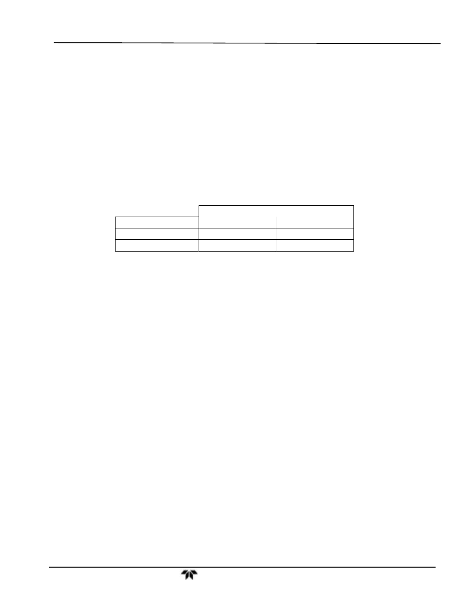
Further confirmation that the pickups and motor are operating properly can be obtained by measuring the
frequency at TP1 and TP2 using a frequency counter, a digital volt meter with a frequency counter, or an
oscilloscope per the table below.
Table 10-9: Opto Pickup Board Nominal Output Frequencies
NOMINAL MEASURED FREQUENCY
AC MAINS FREQ.
TP1
TP2
50 Hz
25
300
60 Hz
30
360
10.5.7.3. GFC Wheel Drive
If the D1 and D2 on the sync demodulator board are not flashing then:
1. Check for power to the motor by measuring between pins 1 and 3 on the connector feeding the
motor. For instruments configured for 120 or 220-240VAC there should be approximately 88
VAC for instruments configured for 100VAC, it should be the voltage of the AC mains,
approximately 100VAC.
2. Verify that the frequency select jumper, JP4, is properly set on the Relay Board. For 50 Hz
operation it should be installed. For 60 Hz operation may either be missing or installed in a
vertical orientation.
3. If there is power to the motor and the frequency select jumper is properly set then the motor is
likely bad. See Section 10.6.2 for instructions on removing and replacing the GFC assembly that
the motor is bolted to.
10.5.7.4. IR Source
The IR source can be checked using the following procedure:
1. Disconnect the source and check its resistance when cold. When new, the source should have a
cold resistance of more than 1.5 Ohms but less than 3.5 Ohms. If not, then the source is bad.
2. With the source disconnected, energize the analyzer and wait for it to start operating. Measure
the drive Voltage between pins 1 and 2 on the jack that the source is normally connected to; it
should be 11.5 ± 0.25 VDC. If not, then there is a problem with either the wiring, the Relay
Board, or the +12V power supply.