Current loop output adjustment – Teledyne GFC-7000T - Trace CO2 Analyzer - manual User Manual
Page 149
Operating Instructions
Model GFC7000TA Carbon Dioxide Analyzer
Teledyne Analytical Instruments
131
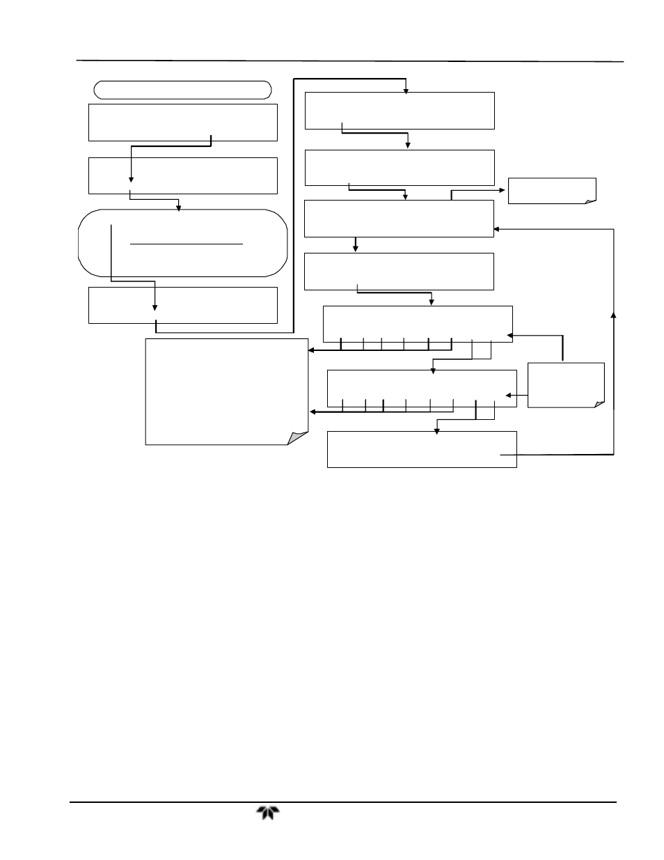
Press SET> to select the analog output channel to be
configured:
DISPLAYED
AS
=
CHANNEL
CONC_OUT_1
=
A1
CONC_OUT_2
=
A2
TEST
OUTPUT
=
A4
DIAG
ANALOG I / O CONFIGURATION
PREV
NEXT
ENTR
EXIT
DIAG AIO
AOUTS CALIBRATED:
NO
< SET
SET>
CAL
EXIT
FROM ANALOG I/O CONFIGURATION MENU
DIAG AIO
CONC_OUT_1 :5V, NO CAL
< SET SET>
EDIT
EXIT
DIAG AIO
CONC_OUT_1 CALIBRATED: YES
< SET
CAL
EXIT
DIAG AIO
CONC_OUT_1 RANGE: 5V
SET>
EDIT
EXIT
DIAG AIO
CONC_OUT_2 CALIBRATED: NO
< SET
CAL
EXIT
DIAG AIO
CONC_OUT_1 VOLT–Z : 0 mV
U100 UP10 UP DOWN DN10 D100
ENTR EXIT
Press to increase / decrease the analog output
by 100, 10 or 1 counts.
Continue adjustments until the voltage measured
at the output of the analyzer and/or the input of
the recording device matches the value in the
upper right hand corner of the display to the
tolerance listed in Table 6-20.
The concentration display will not change. Only
the voltage reading of your voltmeter will change.
DIAG AIO
CONC_OUT_1 VOLT–S : 4500 mV
U100 UP10 UP DOWN DN10 D100
ENTR EXIT
DIAG AIO
CONC_OUT_1 REC OFS: 0 mV
< SET
SET>
EDIT
EXIT
If AutoCal is ON, go to
Section 6.7.3
EXIT
ignores the
new setting.
ENTR
accepts the
new setting.
DIAG AIO
CONC_OUT_1 AUTO CAL: OFF
< SET
SET>
EDIT
EXIT
6.13.4.4. Current Loop Output Adjustment
A current loop option is available and can be installed as a retrofit for each of the analog outputs of the
analyzer (s 5.2). This option converts the DC voltage analog output to a current signal with 0-20 mA
output current. The outputs can be scaled to any set of limits within that 0-20 mA range. However, most
current loop applications call for either 2-20 mA or 4-20 mA range. All current loop outputs have a +5%
over-range. Ranges with the lower limit set to more than 1 mA (e.g., 2-20 or 4-20 mA) also have a -5%
under-range.
To switch an analog output from voltage to current loop after installing the current output printed circuit
assembly, follow the instructions in Section 6.13.4.4 and select CURR from the list of options on the
RANGE menu.
Adjusting the signal zero and span values of the current loop output is done by raising or lowering the
voltage of the respective analog output. This proportionally raises or lowers the current produced by the
current loop option.
Similar to the voltage calibration, the software allows this current adjustment to be made in 100, 10 or 1
count increments. Since the exact current increment per voltage count varies from output to output and
from instrument to instrument, you will need to measure the change in the current with a current meter
placed in series with the output circuit (Figure 6-16).