Analog output calibration mode – Teledyne GFC-7000T - Trace CO2 Analyzer - manual User Manual
Page 144
Operating Instructions
Model GFC7000TA Carbon Dioxide Analyzer
Teledyne Analytical Instruments
126
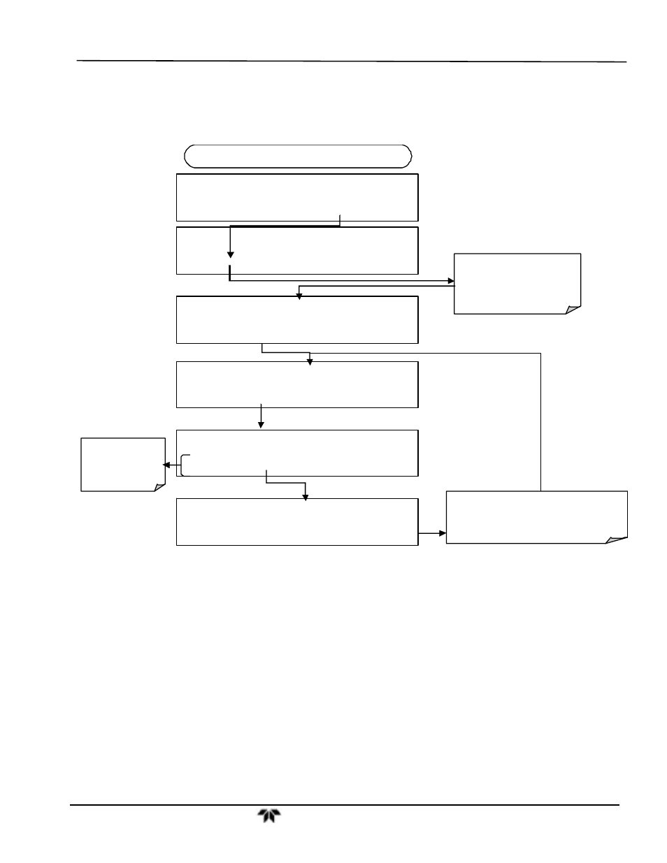
6.13.4.1. Analog Output Signal Type and Range Span Selection
To select an output signal type (DC Voltage or current) and level for one output channel, activate the
ANALOG I/O CONFIGURATION MENU (See Section 6.13.1) then press:
DIAG AIO
CONC_OUT_2 RANGE: 5V
SET>
EDIT
EXIT
DIAG
ANALOG I / O CONFIGURATION
PREV
NEXT
ENTR
EXIT
DIAG AIO
AOUTS CALIBRATED: NO
< SET
SET>
CAL
EXIT
FROM ANALOG I/O CONFIGURATION MENU
DIAG AIO OUTPUT RANGE:
5V
0.1V 1V 5V
10V
CURR
ENTR
EXIT
To set the signal
level and type of
the selected
channel
DIAG AIO
CONC_OUT_2:5V, CAL
< SET SET>
EDIT
EXIT
Press SET> to select the
analog output channel to be
configured. Press EDIT to
continue
Pressing ENTR records the new setting
and returns to the previous menu.
Pressing EXIT ignores the new setting and
returns to the previous menu.
DIAG AIO OUTPUT RANGE:
10V
0.1V 1V 5V
10V
CURR
ENTR EXIT
6.13.4.2. Analog Output Calibration Mode
The analog outputs can be calibrated automatically or manually. In its default mode, the instrument is
configured for automatic calibration of all channels. Manual calibration should be used for the 0.1V range
or in cases where the outputs must be closely matched to the characteristics of the recording device.
Outputs configured for automatic calibration can be calibrated as a group or individually. Calibration of
the analog outputs needs to be carried out on first startup of the analyzer (performed in the factory as part
of the configuration process) or whenever re-calibration is required.