Teledyne GFC-7000T - Trace CO2 Analyzer - manual User Manual
Page 224
Theory of Operation
Model GFC7000TA Carbon Dioxide Analyzer
Teledyne Analytical Instruments
206
9.3.5.3. Zero/Span Valve Options
Any zero/span valve options installed in the analyzer are controlled by a set of electronic switches located
on the relay board. These switches, under CPU control, supply the +12VDC needed to activate each
valve’s solenoid.
9.3.5.4. IR Source
The Relay board supplies a constant 11.5VDC to the IR Source. Under normal operation the IR source is
always on.
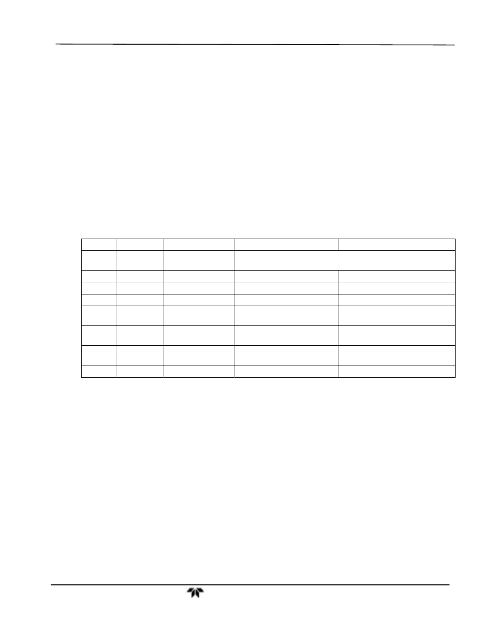
9.3.5.5. Status LEDs
Eight LEDs are located on the analyzer’s relay board to show the current status on the various control
functions performed by the relay board (see Figure 10-14). They are:
Table 9-2: Relay Board Status LED’s
LED
COLOR
FUNCTION
STATUS WHEN LIT
STATUS WHEN UNLIT
D1 RED
Watchdog
Circuit
Cycles On/Off Every 3 Seconds under direct control of the
analyzer’s CPU.
D2
YELLOW
Wheel Heater
HEATING
NOT HEATING
D3
YELLOW
Bench Heater
HEATING
NOT HEATING
D4 YELLOW
Spare
N/A
N/A
D5 GREEN Sample/Cal Gas
Valve Option
Valve Open to CAL GAS
FLOW
Valve Open to SAMPLE GAS
FLOW
D6 GREEN Zero/Span Gas
Valve Option
Valve Open to SPAN GAS
FLOW
Valve Open to ZERO GAS FLOW
D7 GREEN Shutoff Valve
Option
Valve Open to CAL GAS
FLOW
Valve CLOSED to CAL GAS
FLOW
D8
GREEN
IR SOURCE
Source ON
Source OFF