Sample gas flow, Flow rate control, Critical flow orifice – Teledyne GFC-7000T - Trace CO2 Analyzer - manual User Manual
Page 212
Theory of Operation
Model GFC7000TA Carbon Dioxide Analyzer
Teledyne Analytical Instruments
194
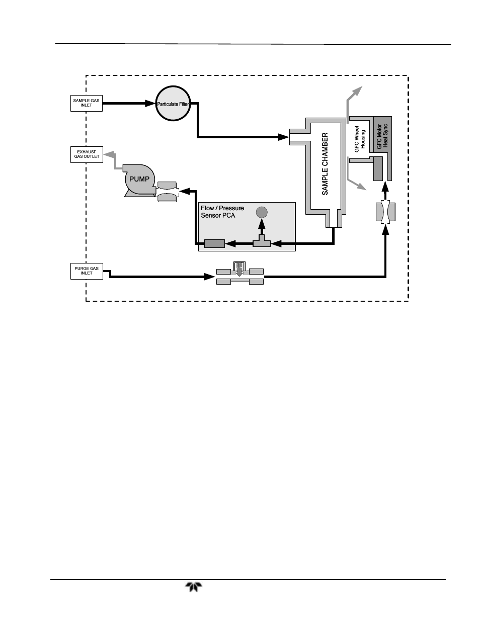
9.2.1. Sample Gas Flow
SAMPLE
PRESSURE
SENSOR
CO
2
FLOW
SENSOR
Sample Gas
Flow Control
Purge Gas
Flow Control
Purge Gas
Pressure Control
Figure 9-7:
Internal Pneumatic Flow – Basic Configuration
9.2.2. Flow Rate Control
To maintain a constant flow rate of the sample gas through the instrument, the Model GFC 7000TA uses
special flow control assemblies located in the purge gas line at the entrance to the GFC wheel housing
and in the exhaust gas line just before the pump (see Figure 10-7). These assemblies consists of:
A critical flow orifice.
Two o-rings: Located just before and after the critical flow orifice, the o-rings seal the gap between
the walls of assembly housing and the critical flow orifice.
A spring: Applies mechanical force needed to form the seal between the o-rings, the critical flow
orifice and the assembly housing.
9.2.2.1. Critical Flow Orifice
The most important component of this flow control assembly is the critical flow orifice.
Critical flow orifices are a remarkably simple way to regulate stable gas flow rates. They operate without
moving parts by taking advantage of the laws of fluid dynamics. By restricting the flow of gas though the
orifice, a pressure differential is created. This pressure differential combined with the action of the
analyzer’s pump draws the gas through the orifice.
As the pressure on the downstream side of the orifice (the pump side) continues to drop, the speed that
the gas flows though the orifice continues to rise. Once the ratio of upstream pressure to downstream