Table, Interrupt controllers – HP A7818-IE002 User Manual
Page 75
System BIOS
BIOS Addresses
Chapter 3
75
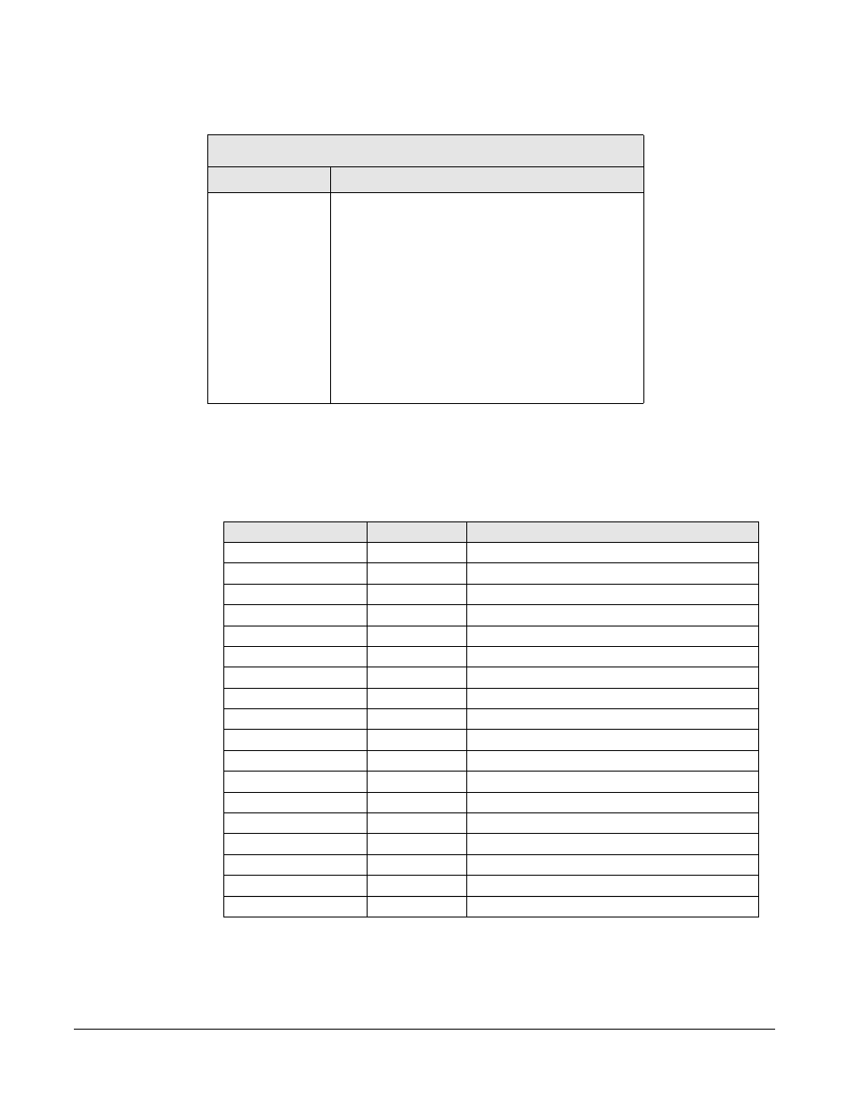
The following table shows how the system allocates DMA channels.
Interrupt Controllers
The system’s interrupt controller is equivalent in function to two 82C59 interrupt
controllers. The following table shows how the interrupts are connected to the APIC
controller. The IRQs are numbered sequentially, starting with the master controller and
followed by the slave (both of 82C59 type).
DMA controller
Channel
Function
DMA 0
Free
DMA 1
Free if not used for parallel port in Setup
DMA 2
Floppy disk drive controller
DMA 3
Free if not used for parallel port in Setup
DMA 4
Used to cascade DMA channels 0-3
DMA 5
Free
DMA 6
Free
DMA 7
Free
I/O APIC Input
IRQ
IRQ Description
INTIN0
ICH
INTIN1
IRQ1
Super I/O keyboard controller
INTIN2
IRQ0
ICH system timer
INTIN3
IRQ3
Super I/O - Used by serial port if enabled
INTIN4
IRQ4
Super I/O - Used by serial port if enabled
INTIN5
IRQ5
Free if not used for parallel port or audio
INTIN6
IRQ6
Super I/O - floppy disk controller
INTIN7
IRQ7
Super I/O - LPT1
INTIN8
IRQ8
ICH - RTC
INTIN9
IRQ9
Available for PCI devices
INTIN10
IRQ10
Available for PCI devices
INTIN11
IRQ11
Available for PCI devices
INTIN12
IRQ12
Super I/O - mouse
INTIN13
IRQ13
Coprocessor
INTIN14
IRQ14
ICH - Integrated IDE Controller (primary)
INTIN15
IRQ15
ICH - Integrated IDE Controller (secondary)
INTIN16
PCINTA
INTIN17
PCINTB