Figure623 installing the new system board – HP A7818-IE002 User Manual
Page 146
Installing Or Replacing Parts And Accessories
Replacing The System Board
Chapter 6
146
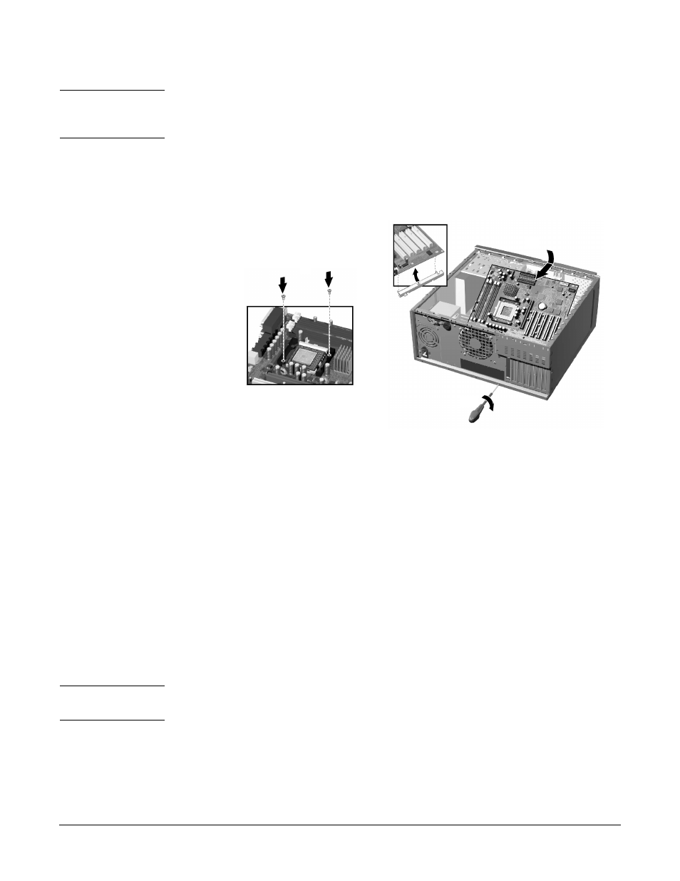
CAUTION
When inserting the system board, be careful not to damage or bend the metal fingers
on the rear connector EMI shield. If the shield is damaged it can be very difficult to
install the system board correctly.
3. Replace the rear screw to secure the system board in place.
4. Replace the two screws located next to the processor socket.
Figure 6-23
Installing the New System Board
5. Reconnect any cables you disconnected earlier from the system board. Note that
there are three power connectors on the system board – you must connect all of
them. To find out the positions of system board connectors, refer to page 152 or to the
label located on the inside of the cover.
6. Replace the main memory, processor, heatsink and any accessory cards in the new
system board (described in this chapter). When reinstalling the heatsink, remember
to replace the thermal interface.
7. Check system board switch 10 to ensure it is correctly set. Also, check that switch 5
is set to ON. Refer to page 147 for more information about system board switches.
8. Replace the chassis beam and secure it in place with the retaining screw. Make sure
the Universal AGP Clip is properly adjusted.
9. Return the workstation to its upright position.
10. Replace the Workstation’s cover (refer to page 119). Reconnect all the power and
telecommunications cables.
11. After installing the system board, you need to update your BIOS.
NOTE
The latest BIOS for your Workstation and instructions on updating the BIOS are
available from:
www.hp.com/go/workstationsupport
.
1
2
3
4