Table, Dma channel controllers – HP A7818-IE002 User Manual
Page 74
System BIOS
BIOS Addresses
Chapter 3
74
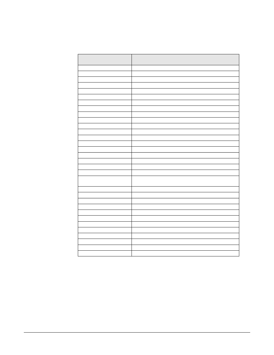
system components. When you install an accessory board, ensure that the selected I/O
address space is in the free area of the space reserved for accessory boards (100h to
3FFh).
DMA Channel Controllers
The system permits only I/O-to-memory and memory-to-I/O transfers. The hardware
configuration doesn’t allow I/O-to-I/O or memory-to-memory transfers.
The system controller supports seven DMA channels, each with a page register that
extends the channel’s addressing range to 16MB.
Default Values for
I/O Address Ports
Function
0000 - 0CF7
DMA controller 1
0020 - 0021
Master interrupt controller (8259)
002E - 002F
Super I/O
0040 - 0043
Timer 1
0060, 0064
Keyboard controller (reset, slow A20)
0061
Port B (speaker, NMI status, and control)
0070
Bit 7: NMI mask register
0070 - 0071
RTC and CMOS
0080
Manufacturing port (POST card)
0081 - 0083, 008F
DMA low page register
0092
PS/2 reset and Fast A20
00A0 - 00A1
Slave interrupt controller
00C0 - 00DF
DMA controller 2
00F0 - 00FF
Coprocessor error
0170 - 0177
Free (IDE secondary channel)
01F0 - 01F7
IDE primary channel
0278 - 027F
LPT 2
02E8 - 02EF
Serial port 4 (COM4)
02F8 - 02FF
Serial port 2 (COM2)
0372 - 0377
Free (IDE secondary channel, secondary floppy disk
drive)
0378 - 037F
LPT1
03B0 - 03DF
VGA
03E8 - 03EF
COM3
03F0 - 03F5
Floppy disk drive controller
03F6
IDE primary channel
03F7
Floppy disk drive controller
03F8 - 03FF
COM1
04D0 - 04D1
Interrupt edge/level control
0778 - 077F
LPT1 ECP
0CF8 - 0CFF
PCI configuration space
C000 -
Power management I/O space and ACPI registers
C100 - C10F
SMBus I/O space