Av-hs60c2/av-hs60c4, 1st line 2nd line, 1st line 2nd line 1st line 2nd line – Panasonic AV-HS6000 2 M/E Live Switcher Main Frame & Control Panel (Dual Redundant Power Supplies) User Manual
Page 137: Switching the me area in the menu panel av‑hs60c3, R av‑hs60c4, Select the button → [operate] → [mechg] tab

– 137 –
Chapter 7 CONFIG Menu — Setting the operation mode
If [AUX1] to [AUX4] are set to [On] in the [AUX Trans] column, select the source signal that is changed by the corresponding KEY bus crosspoint
buttons.
At this time, the MIX transition is performed at the transition time specified in [AUX1] to [AUX4] in the [Trans Time] column.
During transition, KEY crosspoint buttons denoting the transition source lights in the Preset tally color, and the KEY bus crosspoint buttons denoting the
transition target source lights in the Low tally color.
When the transition is completed, the transition source button goes off, and the transition target button lights in the Low color.
When another signal is selected during transition, the transition processing continues from that midway point.
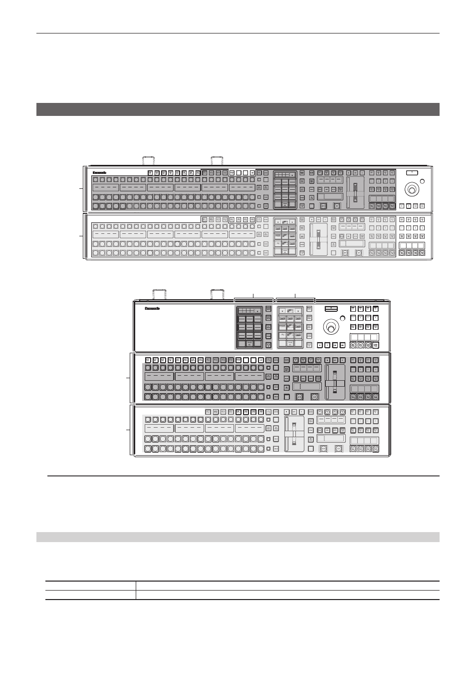
Switching the ME area in the Control Panel AV‑HS60C1/AV‑HS60C2/AV‑HS60C4
Switch the ME1 and ME2 in the Control Panel AV-HS60C1/AV-HS60C2/AV-HS60C4.
f
The following figure shows the area that can be switched.
r
AV‑HS60C1/AV‑HS60C2
CHR
LIN
LUM
FULL
4
SDI
IN3
3
SDI
IN2
2
SDI
IN1
1
Black
24
23
22
21
20
19
18
17
16
15
14
13
12
11
10
SDI
IN9
9
SDI
IN8
SDI
IN11
SDI
IN12
Still
1V
Still
2V
Still
3V
Still
4V
Clip
1V
Clip
2V
Clip
3V
Clip
4V
CBGD
1
ME1
PGM
ME2
PGM
SDI
IN10
8
SDI
IN7
7
SDI
IN6
6
SDI
IN5
5
SDI
IN4
RECALL
STORE
DEL
RECALL
CBGD
STORE
DEL
MIX
02s01f
MIX
01s00f
MIX
01s00f
WIPE
01s00f
CHR
LIN
FULL
FULL
WIPE
01s00f
MIX
01s00f
MIX
01s00f
MIX
CG5V
CG6V
CAM1
CAM2
CG5V
CG6V
CAM1
CAM2
CG1V
CG2V
CG3V
CG4V
01s00f
MIX
ME2
01s00f
MIX
ME1
01s00f
BUS
SHFT
BUS
SHFT
1-7
4-1
1-8
1-9
SHOT000
1-1
SHOT001
1-2
SHOT002
1-3
SHOT003
1-4
1-5
1-6
PLAY
SEL
AUK
DSK
ME2
XPT
ME1
4
SDI
IN3
3
SDI
IN2
2
SDI
IN1
1
Black
24
23
22
21
20
19
18
17
16
15
14
13
12
11
10
SDI
IN9
9
SDI
IN8
SDI
IN11
SDI
IN12
Still
1V
Still
2V
Still
3V
Still
4V
Clip
1V
Clip
2V
Clip
3V
Clip
4V
CBGD
1
ME1
PGM
ME2
PGM
SDI
IN10
8
SDI
IN7
7
SDI
IN6
6
SDI
IN5
5
SDI
IN4
4-3
4-2
4-4
4-6
4-5
4-7
4-9
4-8
OP
STILL1
1st Line
2nd Line
r
AV‑HS60C4
CHR
LIN
LUM
FULL
4
SDI
IN3
3
SDI
IN2
2
SDI
IN1
1
Black
16
15
14
13
12
11
10
SDI
IN9
9
SDI
IN8
SDI
IN11
SDI
IN12
Still
1V
Still
2V
Still
3V
SDI
IN10
8
SDI
IN7
7
SDI
IN6
6
SDI
IN5
5
SDI
IN4
RECALL
STORE
DEL
RECALL
CBGD
STORE
DEL
MIX
02s01f
MIX
01s00f
MIX
01s00f
WIPE
01s00f
CHR
LIN
FULL
FULL
WIPE
01s00f
MIX
01s00f
MIX
01s00f
MIX
CG5V
CG6V
CAM1
CAM2
CG5V
CG6V
CAM1
CAM2
CG1V
CG2V
CG3V
CG4V
01s00f
MIX
ME2
01s00f
MIX
ME1
01s00f
BUS
SHFT
BUS
SHFT
1-7
4-1
1-8
1-9
SHOT000
1-1
SHOT001
1-2
SHOT002
1-3
SHOT003
1-4
1-5
1-6
PLAY
SEL
AUK
DSK
ME2
XPT
ME1
4
SDI
IN3
3
SDI
IN2
2
SDI
IN1
1
Black
16
15
14
13
12
11
10
SDI
IN9
9
SDI
IN8
SDI
IN11
SDI
IN12
Still
1V
Still
2V
Still
3V
SDI
IN10
8
SDI
IN7
7
SDI
IN6
6
SDI
IN5
5
SDI
IN4
4-3
4-2
4-4
4-6
4-5
4-7
4-9
4-8
OP
STILL1
1st Line
2nd Line
1st Line
2nd Line
@
@
NOTE
t
and Menu Panel AV-HS60C3 are not subject for switching.
t
If you perform switching using the KEY bus selector buttons on the upper ME line (1st Line) while
the selection status of the KEY bus crosspoint buttons on the lower ME line (2nd Line) takes over the KEY bus crosspoint buttons on the upper ME
line (1st Line) before switching, and the KEY bus selector button lamps all turn off. Press the KEY bus selector buttons on the lower ME line (2nd Line)
to turn on the lamps and change the operation targets of the KEY bus crosspoint buttons to the appropriate bus.
Switching the ME area in the Menu Panel AV‑HS60C3
1
Select the
→
[OPERATE]
→
[MECHG] tab.
2
Select an item in [1st Line] and [2nd Line] in the [MainPanel]/[SubPanel1]/[SubPanel2] column.
[ME1]
The corresponding ME area is used as ME1.
[ME2]
The corresponding ME area is used as ME2.
f
If the item set for [ME1] is switched to [ME2], the item selected for [ME2] is switched to [ME1].
