Avago Technologies Cache Protection for RAID Controller Cards User Manual
Page 73
Avago Technologies
- 73 -
Cache Backup Products for MegaRAID SAS+SATA RAID Controllers User Guide
May 2015
Chapter 2: Installing the Cache Backup Products
Installing the LSIiBBU08 Unit
2.5.6.3
Connecting the Cable Between the LSIiBBU08 Unit on the Remote Mount Board and the Adapter Card on the
RAID Controller
Follow these steps to connect the cable between the LSIiBBU08 unit on the remote mount board and the
board-to-board adapter card on the RAID controller.
1.
With the controller on a flat, clean, static-free surface, ground yourself, and make sure that the system
is grounded.
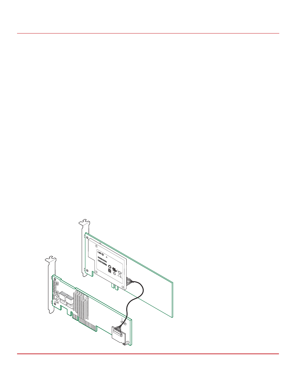
2.
Insert the 20-pin cable connector at one end of the 12-in. cable into the 20-pin J2 cable connector on the
LSIiBBU08 unit on the remote mount board, as shown in the following figure.
3.
Insert the 20-pin cable connector at the other end of the 12-in. cable into the 20-pin J1 connector on the
board-to-board cable adapter card that is installed on the RAID controller, as shown in the following figure.
Black triangles on the connectors help you install the connectors correctly. Insert the cable connectors into the
controller connector and the iBBU connector so that the black triangles are aligned, as shown in the
following figure.
CAUTION
Damage to the battery backup unit will occur when power is applied
to the system if the cable assembly connectors are installed backwards
in either the J1 connector on the board-to-board cable adapter card or
on the J2 BBU connector. The cable connectors are polarized, and the
keying features of the connector are designed to allow the connectors
to be attached in only one orientation. The cable end inserts into the
connector with only minimal resistance.
Even with the keying features, if excessive force is used, it is possible
to install these connectors incorrectly. To assist in correct alignment,
the small triangles that designate pin 1 on each connector are marked
in black. Make sure these triangles line up as shown in the
illustrations. The wire that connects to pin 1 of each end of the cable
assembly is yellow on most Avago cables.
Figure 46 Connecting the LSIiBBU08 Unit on the Remote Mount Board to the Board-to-Board Cable Adapter
3_00749-00
Mo
del:
BA
T 1
S1P
Mo
del:
BA
T 1
S1P
WA
RN
IN
G:
The
ba
tte
ry u
sed
in
this
dev
ice m
ay p
res
en
t a r
isk o
f fir
e o
r
che
mic
al b
urn
if m
istr
eate
d. D
O N
OT
dis
sem
ble
, he
at a
bov
e 6
0C
, c
rus
h o
r
pun
ctu
re,
sho
rt c
irc
uit e
xte
rna
l co
nta
cts
,
or d
ispo
se in
fire
or w
ate
r.
WA
RN
ING
:
The
ba
ttery
use
d in
this
de
vice
m
ay p
res
ent
a ris
k o
f fire
or
che
mic
al b
urn
if m
istre
ate
d. D
O N
OT
diss
em
ble
, he
at a
bov
e 6
0C
, cru
sh o
r
pun
ctu
re, s
hort
circ
uit e
xte
rna
l co
nta
cts,
or d
ispo
se in
fire
or w
ate
r.
Con
tain
s:
So
ny U
S454
261
A8T
Cell
Rec
harg
eab
le Li
-Po
lym
er
Ba
ttery
Pa
ck
Rati
ng:
3.7
V; 1
.59
Ah;
5.9W
h
Fin
ishe
d in
Ch
ina
Con
tain
s:
Son
y U
S45
426
1A
8T
Cell
Rec
harg
eab
le L
i-P
olym
er
Batt
ery
Pa
ck
Rati
ng:
3.7
V; 1
.59
Ah;
5.9
W
h
Fin
ishe
d in
Ch
ina
BB
U P
/N: L4
-25
34
3-04
BB
U P
/N: L
4-2
534
3-0
4
BB
U S
/N:SY
027
002
25S
O
BB
U S
/N:S
Y02
700
225
SO
Li-io
n
Li-io
n
5