Warning, V/f w/ pg start-up – Yaskawa F7 Drive User Manual User Manual
Page 92
Start-Up 4 - 7
V/F w/ PG Start-Up
1-8. See Drive Start-Up Procedures on Page 4-5.
9.
Apply input power to the Drive.
10. Set the control method of the Drive to V/F w/ PG Feedback Control by pressing the MENU key twice for the Quick
Setting menu. Press the ENTER key to display A1-02 “Control Method”. Use the UP and DOWN keys and the
DATA/ENTER key to set this parameter to “1: V/F w/PG Fdbk”. Ensure the DATA/ENTER key is pressed to enter
the selection in the Drive. “Entry Accepted” will briefly appear.
11. Set the Drive input voltage measured in Step 1. In the Quick Setting menu, go to parameter E1-01“Input Voltage”.
This parameter sets the nominal input voltage the Drive will receive.
12. Select an appropriate V/F pattern per the application. Press the UP key once to display parameter E1-03
“V/F Selection”. To set this parameter press the DATA/ENTER key once. Use the UP and DOWN keys and the
DATA/ENTER key to set this parameter per the application. A standard V/F pattern for a 60Hz motor is “1: 60Hz
Saturation”.
13. Set the PG Pulses/Rev of the PG (Encoder) to the correct value. In the Quick Setting menu, go to parameter F1-01
“PG Pulses/Rev”. Use the UP, DOWN, and RESET keys and the DATA/ENTER key to set the encoder PPR.
14. Display motor speed monitor U1-05 “Motor Speed” in the Operation menu.
15. Rotate the motor shaft by hand in the forward direction for the machine. A low positive speed should be displayed
(PG-B2, PG-X2, PG-W2). As the shaft is turned in reverse, a low negative speed should be displayed. If the speed
doesn’t change when the motor shaft is rotated, check the encoder wiring and connections. If the polarity is wrong,
swap A+ and A- wires (terminals 4 and 5 on the PG-X2).
16. Set the Drive to Local control. Press the MENU key once to display the Operation menu. Then, press DATA/
ENTER to display “Frequency Reference”. Press the LOCAL/REMOTE key once. This puts the Drive in the Local
Mode, allowing run/stop and speed commands by the Digital Operator. The AUTO SEQ and AUTO REF indicators
turn off, and the FWD light turns on.
17. Display monitor U1-01 “Frequency Ref” in the Operation menu.
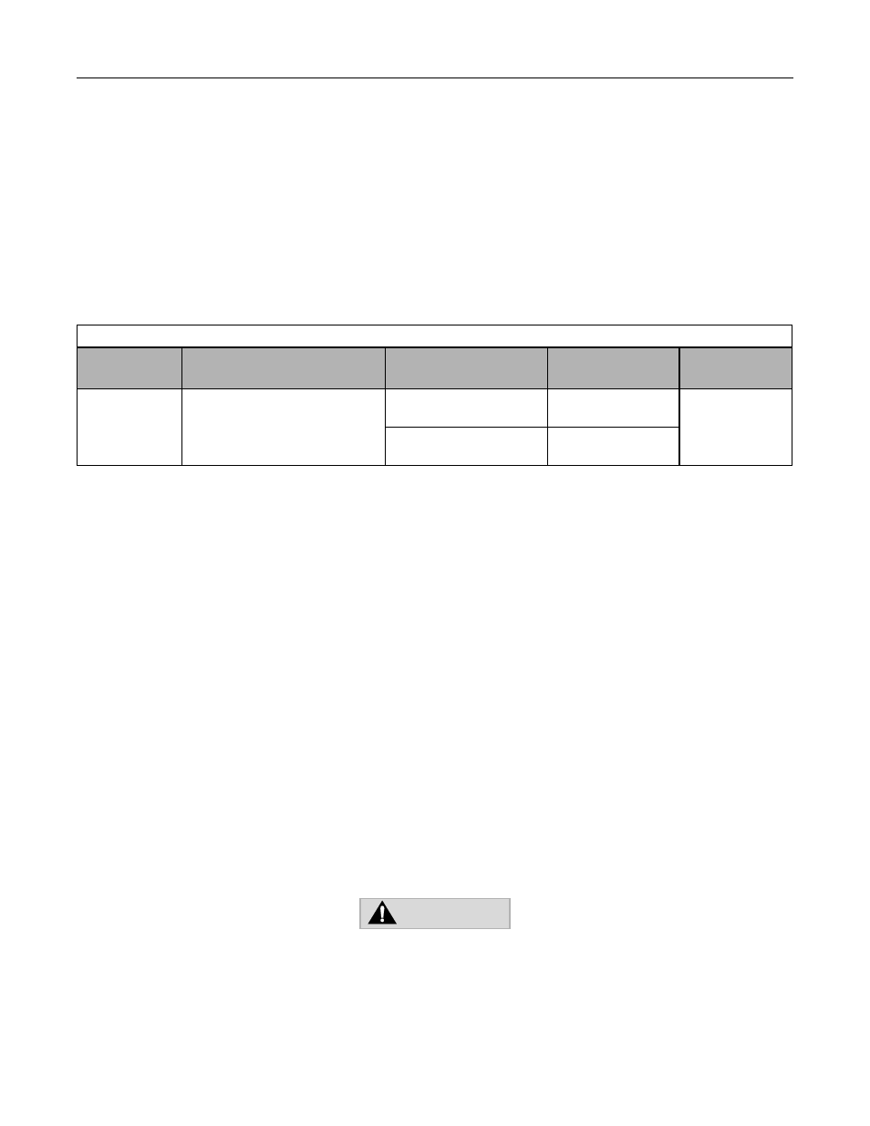
Table 4.4 Input Voltage Setting
Parameter
No.
Parameter Name
Digital Operator Display
Setting Range
Factory Setting
Menu Location
E1-01
Input Voltage Setting
Input Voltage
155.0 to 255.0
(208-240Vac)
240.0
(208-240Vac)
Quick Setting
or
Programming
310.0 to 510.0
(480Vac)
480.0
(480Vac)
THE NEXT KEY-PRESS WILL CAUSE THE MOTOR TO ROTATE.
TAKE APPROPRIATE PRECAUTIONS.
WARNING