Electrical installation 2 - 37, Pg-x2, Wiring the pg-x2 – Yaskawa F7 Drive User Manual User Manual
Page 64
Electrical Installation 2 - 37
PG-X2
The terminal specifications for the PG-X2 are given in Table 2.21.
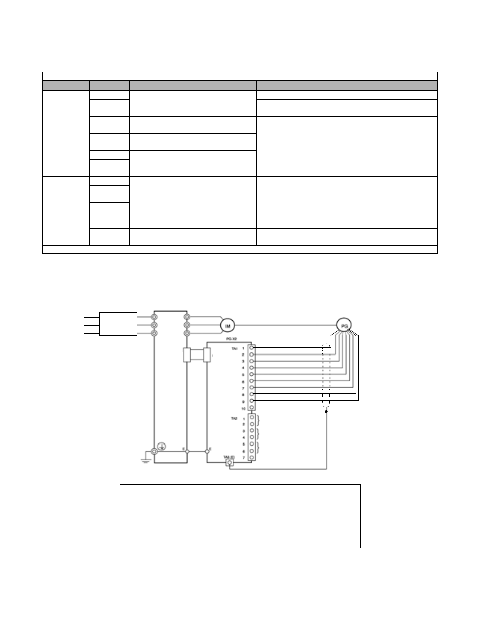
Wiring the PG-X2
Wiring examples are provided in Fig 2.22 for the PG-X2.
Fig 2.22 PG-X2 Wiring
Table 2.21 PG-X2 Terminal Specifications
Terminal
No.
Contents
Specifications
TA1
1
Power supply for pulse generator
12Vdc (±5%), 200mA max.*
2
0Vdc (GND for power supply)
3
5Vdc (±5%), 200mA max.*
4
A-phase input terminals
Line driver input (RS-422 level)
Maximum response frequency: 300kHz
5
6
B-phase input terminals
7
8
Z-phase input terminals
9
10
Common terminal
0Vdc (GND for power supply)
TA2
1
A-phase output terminals
Line driver output (RS-422 level)
2
3
B-phase output terminals
4
5
Z-phase output terminals
6
7
Control circuit common
Isolated control circuit GND
TA3
(E)
Shield connection terminal
-
* 5Vdc and 12Vdc cannot be used at the same time.
Drive
Power supply +12Vdc
Power supply +5Vdc
A-phase pulse input (+)
A-phase pulse input (-)
B-phase pulse input (+)
B-phase pulse input (-)
A-phase pulse monitor output
B-phase pulse monitor output
Z-phase pulse monitor output
R/L1
S/L2
U/T1
V/T2
W/T3
T/L3
4CN
4CN
R/L1
S/L2
T/L3
Branch
Circuit
Protection
Power supply 0Vdc
Z-phase pulse input (+)
Z-phase pulse input (-)
•
Shielded twisted-pair wires must be used for signal lines.
•
Do not use the PG-X2's power supply for anything other than the pulse generator (encoder).
Using it for another purpose can cause malfunctions due to noise.
•
The length of the pulse generator's wiring must not be more than 100 meters.
•
The direction of rotation of the PG can be set in parameter F1-05 (PG Rotation).
The factory preset is for motor forward rotation, A-phase advancement.