Modbus self-diagnosis, Communications d - 18 – Yaskawa F7 Drive User Manual User Manual
Page 237
Communications D - 18
Modbus Self-Diagnosis
The Drive has a built-in function for self-diagnosing the operations of the serial communication interface circuits. The
self-diagnosis function tests the serial communications hardware of the Drive by jumpers the send and receive terminals to
receive the same message as the Drive sends.
Perform the self-diagnosis function using the following procedure.
1. Turn ON the power supply to the Drive, and set parameter H1-05 (Terminal S7 function selection) to 67 (communication
test mode).
2. Turn OFF the power supply to the Drive.
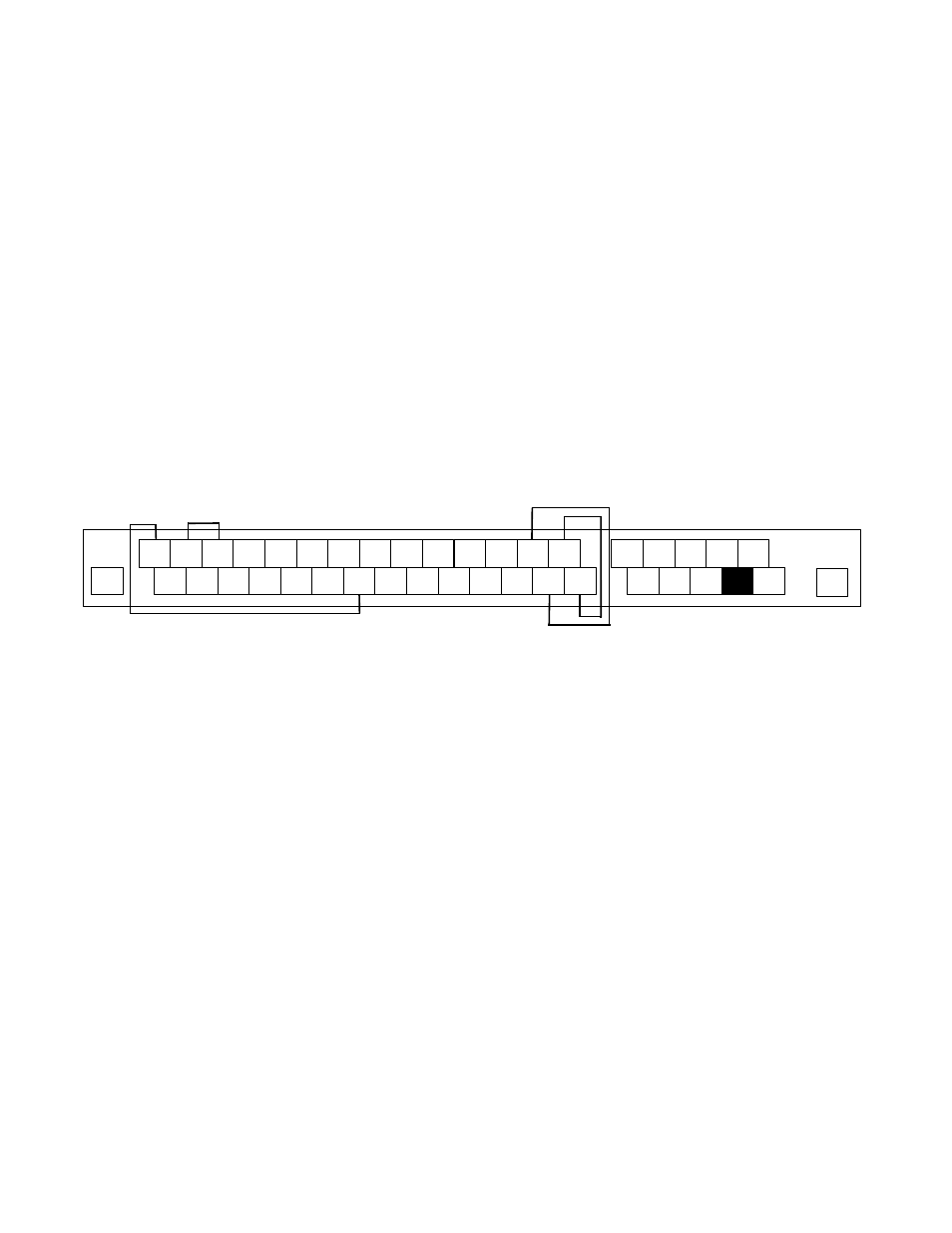
3. Jumper the following terminals while the power supply is turned OFF (see diagram below):
Connect S+ to R+.
Connect S- to R-.
Connect S7 to SN.
4. Turn ON the terminating resistor. (Turn ON pin 1 on DIP switch 1).
5. Turn ON the power supply to the Drive again.
Fig D.10 Communication Terminal Connection for Self -Diagnosis Function
6. During normal self-diagnostic operation, the Digital Operator displays the frequency reference value. If an error occurs, a
CE (Modbus communication error) alarm will be displayed on the Digital Operator, the fault contact output will be turned
ON, and the Drive operation ready signal will be turned OFF.
SN
SC
SP
A1
A2
+V
AC
-V
A3
MP
AC
RP
R+
R-
MC
M5
M6
MA MB
S1
S2
S3
S4
S5
S6
S7
S8
FM
AC
AM
IG
S+
S-
M2
M3
M4
M1
E(G)
E(G)