Ok not ok – Yaskawa F7 Drive User Manual User Manual
Page 38
Electrical Installation 2 - 11
Cable Length between Drive and Motor
The F7 should be installed as close as possible to the motor to minimize the length of the load side power cable needed
between the Drive and motor.
If the cable between the Drive and the motor is long, the high-frequency leakage current will increase, causing the Drive
output current to increase as well. This may affect peripheral devices. To prevent this, reduce cable length, or if necessary,
adjust the carrier frequency (set in parameter C6-02) as shown in Table 2.7.
The line side power cables, load side power cables and control wiring should be run in seperate conduit. Careful attention to
this recommended design practice will avoid many potential motor and Drive related problems.
Ground Wiring
Observe the following precautions when connecting the ground wire:
1. 208-240Vac Drives should have a ground connection with resistance of less than 100
Ω
.
2. 480Vac Drives should have a ground connection with resistance of less than 10
Ω
.
3. Do not share the ground wire with other devices, such as welding machines or large-current electrical equipment.
4. Always use a ground wire that complies with technical standards on electrical equipment and minimize the length of the
ground wire. Leakage current flows through the Drive. Therefore, if the distance between the ground rod and the ground
terminal is too long, potential on the ground terminal of the Drive could develop.
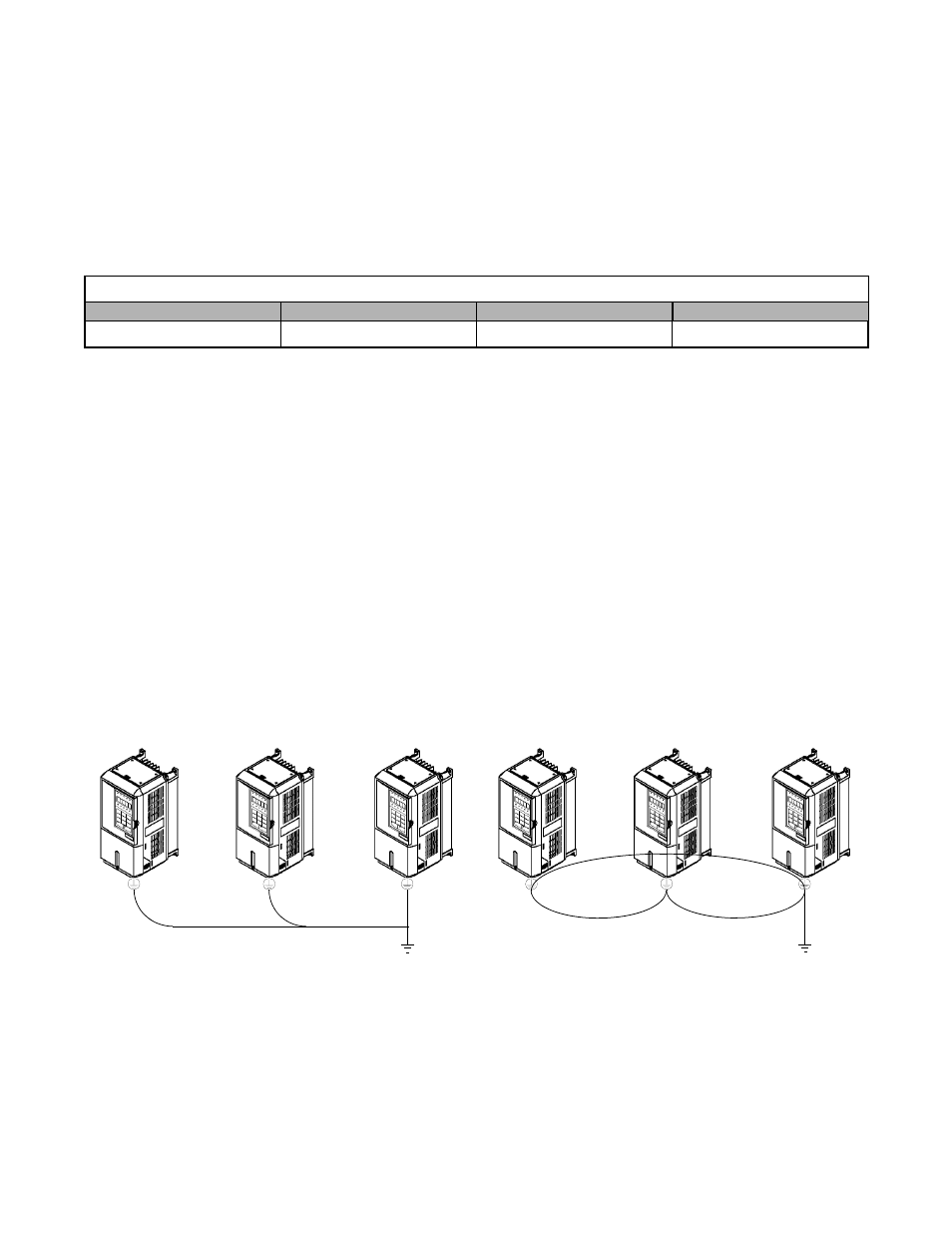
5. When using more than one Drive, be careful not to loop the ground wire. See Fig 2.4.
Fig 2.4 Ground Wiring Examples
Table 2.7 Motor Cable Length vs. Carrier Frequency
Motor Cable Length
164 ft. (50m) maximum
328 ft. (100m) maximum
More than 328 ft.(100m)
Carrier Frequency
15kHz maximum
10kHz maximum
5kHz maximum
OK
NOT OK