Electrical installation 2 - 14 – Yaskawa F7 Drive User Manual User Manual
Page 41
Electrical Installation 2 - 14
Remote Mount Resistor Unit Installation Using Internal Braking Transistor
(for F7U20P4 thru F7U2018 and F7U40P4 thru F7U4018)
Since the Remote Mount Resistor Unit generates heat during dynamic braking operation, install it in a location away from
other equipment.
1. Install the Remote Mount Resistor Unit to a noncombustible surface, maintaining a minimum 1.97 inches (50mm)
clearance on each side and a minimum 7.87 inches (200mm) clearance on top.
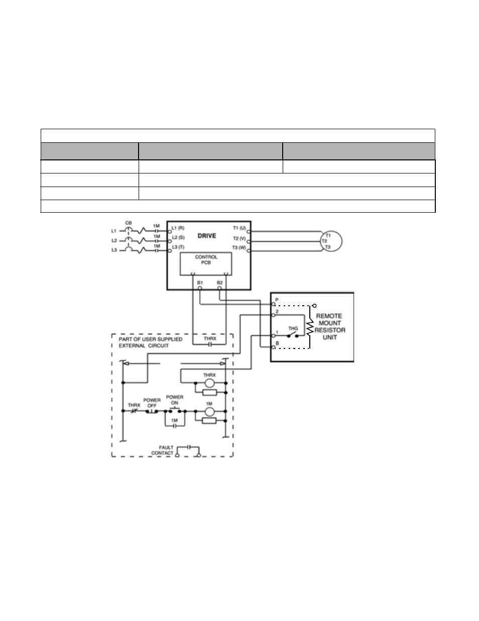
2. Remove the Remote Mount Resistor Unit cover to access its terminal block. Connect the Remote Mount Resistor Unit to
the Drive and to external control circuitry according to the figure below.
Fig 2.6 Wiring Remote Mount Resistor Unit (for F7U20P4 thru F7U2018 and F7U40P4 thru F7U4018)
3. Reinstall and secure Remote Mount Resistor Unit cover and Drive front cover.
4. Proceed to “Adjustments” section on Page 2-18.
Table 2.9 Wire Size for Remote Mount Resistor Unit
Terminals
B, P, R1, R2
1, 2*
Wire Size (AWG)
12-10
18-14*
Wire Type
600V Ethylene propylene rubber insulated, or equivalent
Terminal Screw
M4
* Power Leads for the Remote Mount Resistor Unit generate high levels of electrical noise - these signal leads must be grouped separately.
IM
S3
SN
‡
(R2)*
(R1)*
3% DUTY CYCLE
RESISTOR ASSEM-
*
Terminal markings in parentheses
are for resistors manufactured by
Powerohm Resistors Inc.
‡
Applies when SC is jumpered to SP
and S3 is programmed as External
Fault.
120 VAC