Speed command source, Speed command source -3 – Yaskawa F7 Drive User Manual User Manual
Page 104
Basic Programming 5 - 3
Speed Command Source
b1-01 Reference Source Selection
In order to run the Drive and motor in REMOTE mode, the Drive must receive a run command and a speed command from an
external source. Parameter b1-01 specifies from where the speed command will be accepted. To switch into the “REMOTE”
mode press the LOCAL/REMOTE button on the Digital Operator while the Drive is stopped.
To have the Drive follow the speed command set by the Digital Operator:
Set b1-01=0. The speed command can then be entered into the U1-01 monitor or in parameter d1-01.
To have the Drive follow an analog speed command:
Set b1-01 = 1 and connect a 0 to 10Vdc or -10 to +10Vdc signal to terminals A1 and AC. Be sure to set parameter H3-01 to the
proper setting. Or, connect a 4 – 20mA signal to terminals A2 and AC. Make sure the S1-2 switch and corresponding parameter
H3-08 is properly set up when using terminal A2
To have the Drive receive the speed command from Modbus serial communication:
Set b1-01 = 2 and connect the RS-485/422 serial communications cable to terminals R+, R-, S+, and S- on the removable
terminal block. Make sure the S1-1 switch and the Modbus H5 parameters are properly set.
To use an option board to input the speed command:
Set b1-01 = 3 and install a communications analog input, or digital input option board into the 2CN port on the Drive control
board. Consult the manual supplied with the option board for instructions on integrating the Drive and communications option
board.
To use pulse train to input a speed command:
Set b1-01 = 4 and connect the pulse train signal to terminals RP and AC. Make sure the H6 parameters are properly set.
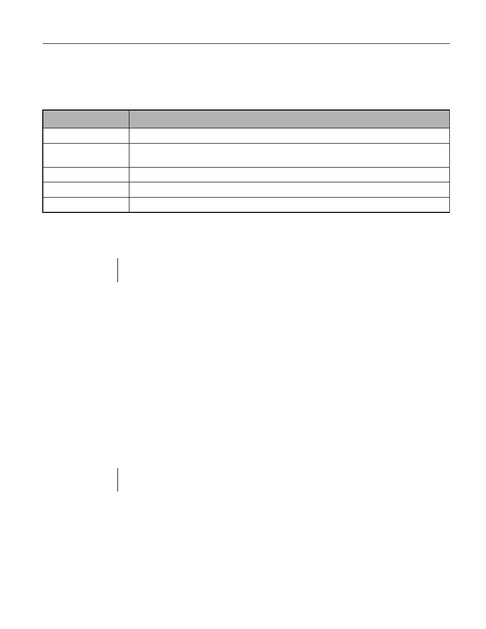
Setting
Description
0
Operator - Monitor U1-01 or parameter d1-01
1
Terminals - Analog input terminal A1 (Terminal A2 sums together with terminal A1 when H3-09=0)
(factory default)
2
Modbus Serial Communication - RS-422/485 terminals R+, R-, S+, and S-
3
Option Board - Option board connected on 2CN
4
Pulse Train Input - Terminal RP and AC
IMPORTANT
If the set speed command is less than the minimum output frequency (E1-09) with a run command input, the
RUN indicator on the Digital Operator will turn on and the STOP indicator on the Digital Operator will blink.
IMPORTANT
If b1-01=3 but an option board is not installed in 2CN, an OPE05 Fault will be displayed on the digital
operator and the Drive will not run.