Communications d - 13 – Yaskawa F7 Drive User Manual User Manual
Page 232
Communications D - 13
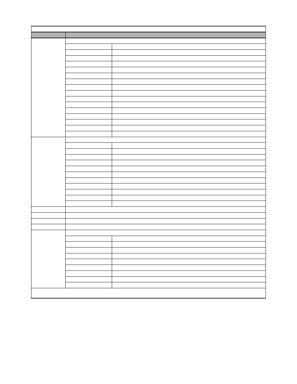
0019H
Alarm content 1
Bit 0
Undervoltage (UV)
Bit 1
Overvoltage (OV)
Bit 2
Heatsink overtemperature (OH)
Bit 3
Drive overheat fault (OH1)
Bit 4
Overtorque 1 detection (OL3)
Bit 5
Overtorque 2 detection (OL4)
Bit 6
2-wire sequence input (EF)
Bit 7
External Baseblock (BB)
Bit 8
External fault 3 (EF3)
Bit 9
External fault 4 (EF4)
Bit A
External fault 5 (EF5)
Bit B
External fault 6 (EF6)
Bit C
External fault 7 (EF7)
Bit D
External fault 8 (EF8)
Bit E
Cooling fan (FAN)
Bit F
Overspeed (OS)
001AH
Alarm content 2
Bit 0
Speed deviation (DEV)
Bit 1
PG open (PGO)
Bit 2
Operator disconnected (OPR)
Bit 3
Modbus communication (CE)
Bit 4
Bus error (BUS)
Bit 5
Waiting for transmission (CALL)
Bit 6
Motor overload (OL1)
Bit 7
Drive overload (OL2)
Bit 8
SI-R/G alarm (E-15)
Bit 9
External fault (EF0)
Bits A to F
Not used
001BH
Not used
001CH
Not used
001DH
Not used
001FH
Not used
0020H
Drive status
Bit 0
Operation: Operating = 1 Stopped = 0
Bit 1
Reverse operation: Reverse operation 0: Forward operation
Bit 2
Drive start-up complete: Completed = 1 Not completed = 0
Bit 3
Fault: Fault = 1
Bit 4
Data setting error: Error = 1
Bit 5
Multi-function digital output 1 (terminal M1 - M2): ON = 1 OFF = 0
Bit 6
Multi-function digital output 2 (terminal M3 - M4): ON = 1 OFF = 0
Bit 7
Multi-function digital output 3 (terminal M5 - M6): ON = 1 OFF = 0
Bits 8 to F
Not used
Note: Communication error details are stored until an error reset is input (errors can be reset while the Drive is operating).
Note: Write 0 to all unused bits. Do not write data to reserved or “Not Used” registers and bits.
Table D.5 Monitor Data (Continued)
Register No.
Contents