Main circuit terminal functions – Yaskawa F7 Drive User Manual User Manual
Page 36
Electrical Installation 2 - 9
Main Circuit Terminal Functions
Main circuit terminal functions are summarized according to terminal symbols in Table 2.4. Wire the terminals correctly for
the desired purpose.
Main Circuit Configurations 208-240Vac
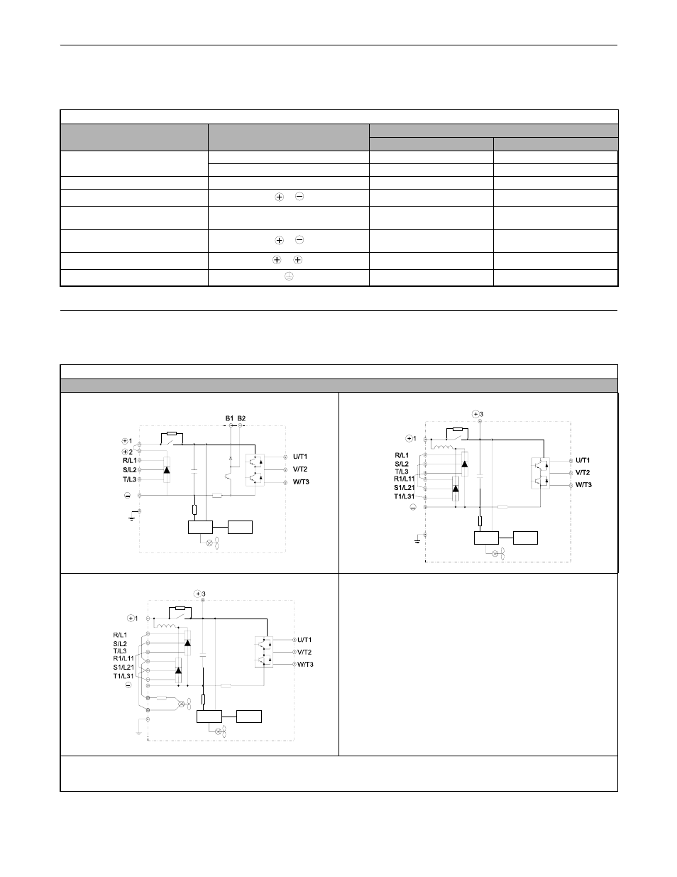
The 208-240Vac main circuit configurations of the Drive are shown in Table 2.5.
Table 2.4 Main Circuit Terminal Functions (208-240Vac and 480Vac)
Purpose
Terminal Designation
Model: CIMR-F7UF F F F
208-240Vac
480Vac
Main circuit power input
R/L1, S/L2, T/L3
20P4 to 2110
40P4 to 4300
R1/L11, S1/L21, T1/L31
2022 to 2110
4030 to 4300
Drive outputs
U/T1, V/T2, W/T3
20P4 to 2110
40P4 to 4300
DC power input
1,
20P4 to 2110
40P4 to 4300
Braking Resistor
Unit Connection
B1, B2
20P4 to 2018
40P4 to 4018
Braking Transistor
Unit Connection
3,
2022 to 2110
4022 to 4300
DC link choke connection
1, 2
20P4 to 2018
40P4 to 4018
Ground
20P4 to 2110
40P4 to 4300
Table 2.5 Drive Main Circuit Configurations
208-240Vac
-
*1 Input fuses or molded case circuit breakers are required for proper branch circuit protection for all Drives. Failure to use
recommended fuses/circuit breakers (See Appendix E) may result in damage to the Drive and/or personal injury.
*2 Consult your Yaskawa representative before using 12-pulse rectification circuit configuration.
Power
supply
Control
circuits
CIMR-F7U20P4 to 2018
{
* 1
CIMR-F7U2022 and 2030
Power
supply
Control
circuits
{
*1, 2
CIMR-F7U2037 to 2110
Power
supply
Control
circuits
{
*1, 2