Electrical installation 2 - 8 – Yaskawa F7 Drive User Manual User Manual
Page 35
Electrical Installation 2 - 8
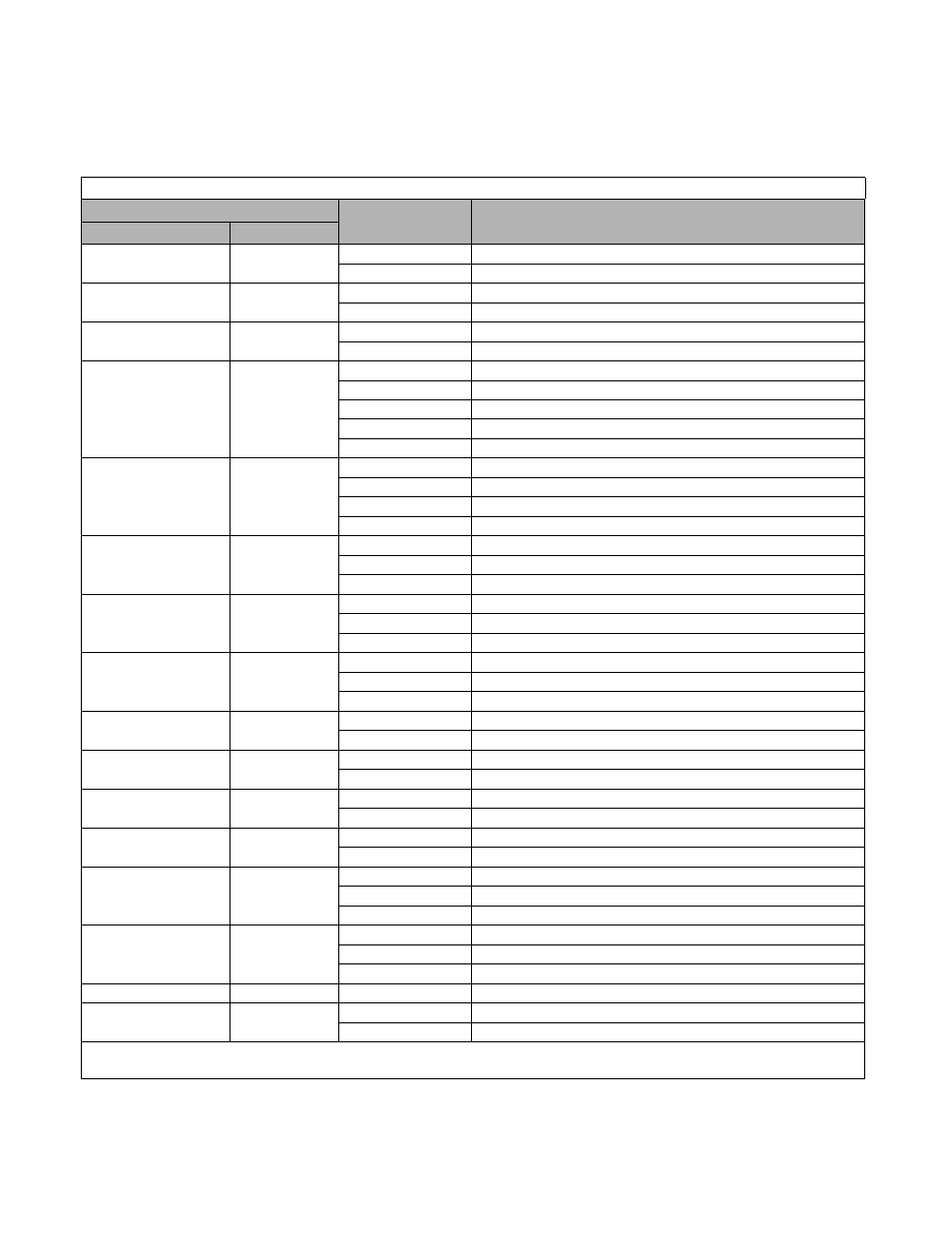
The use of UL listed closed-loop connectors or CSA certified ring connectors sized for the selected wire gauge is
recommended to maintain proper clearances when wiring the Drive. Install connectors per manufacturer recom-
mendation using the correct crimp tool. Table 2.3 lists a suitable closed-loop connector manufactured by JST Cor-
poration.
Table 2.3 Recommended Connectors for Terminal Connections
Wire Size *
Terminal Screw
Ring Tongue (R-Type) Closed-Loop Connectors (Lugs)
JST Corporation Part Numbers **
AWG
mm
2
20
0.5
M3.5
1.25 - 3.7
M4
1.25 - 4
18
0.75
M3.5
1.25 - 3.7
M4
1.25 - 4
16
1.25
M3.5
1.25 - 3.7
M4
1.25 - 4
14
2
M3.5
2 - 3.7
M4
2 - 4
M5
2 - 5
M6
2 - 6
M8
2 - 8
12 / 10
3.5 / 5.5
M4
5.5 - 4
M5
5.5 - 5
M6
5.5 - 6
M8
5.5 - 8
8
8
M5
8 - 5
M6
8 - 6
M8
8 - 8
6
14
M5
14 - 5
M6
14 - 6
M8
14 - 8
4
22
M5
22 - 5
M6
22 - 6
M8
22 - 8
3 / 2
30 / 38
M6
38 - 6
M8
38 - 8
1 / 1/0
50 / 60
M8
60 - 8
M10
60 - 10
2/0
70
M8
70 - 8
M10
70 - 10
3/0
80
M10
80 - 10
M16
80 - 16
4/0
100
M10
100 - 10
M12
100 - 12
M16
100 - 16
250 / 300MCM
125 / 150
M10
150 - 10
M12
150 - 12
M16
150 - 16
400MCM
200
M12
200 - 12
650MCM
325
M12 x 2
325 - 12
M16
325 - 16
*
Wire sizes are based on 75 degrees Celsius copper wire.
** Equivalent connector can be used.