Electrical installation 2 - 21 – Yaskawa F7 Drive User Manual User Manual
Page 48
Electrical Installation 2 - 21
Analog
Output
Signals
FM
Output frequency
0 to +10Vdc / 100% frequency
-10 to +10Vdc / 100% frequency
4 to 20mA / 100% frequency
Multi-function
analog output 1.
Function set by
H4-01.
0 to +10Vdc
-10 to +10Vdc
(Max current 2mA)
4 to 20mA, 500
Ω
AM
Output current
0 to +10Vdc / 100% Drive's rated
output current
-10 to +10Vdc / 100% Drive's
rated output current
4 to 20mA / 100% Drive's rated
output current
Multi-function
analog output 2.
Function set by
H4-04.
AC
Analog common
–
-
Pulse I/O
RP
Pulse input
Pulse input frequency reference
Function set by
H6-01.
0 to 32kHz (3k
Ω) ±5%
High level voltages
3.5 to 13.2
Low level voltages
0.0 to 0.8
Duty Cycle (on/off)
30% to 70%
MP
Pulse monitor
Pulse output frequency
Function set by
H6-06.
0 to 32kHz
+5V output
(Load: 1.5k
Ω)
RS-485/
422
R+
Modbus
communication input
For 2-wire RS-485, jumper R+ and S+ and
jumper R- and S-.
Differential input,
PHC isolation
R-
S+
Modbus
communication output
Differential output,
PHC isolation
S-
IG
Signal common
–
–
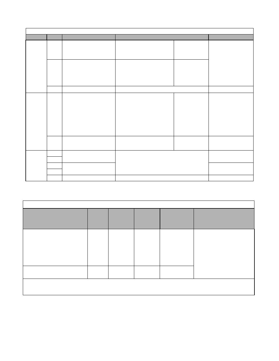
Table 2.12 Terminal Numbers and Wire Sizes (Same for all Drives)
Terminals
Terminal
Screws
Tightening
Torque
lb-in
(N•m)
Possible
Wire Sizes
AWG (mm
2
)
Recommended
Wire Size AWG
(mm
2
)
Wire Type
S1, S2, S3, S4, S5, S6, S7, S8, SN,
SC, SP, +V, -V, A1, A2, A3, AC, RP,
M1, M2, M3, M4, M5, M6, MA, MB,
MC, FM, AC, AM, MP, R+, R-, S+,
S-, IG
Phoenix
type
*3
4.2 to 5.3
(0.5 to 0.6)
Stranded
wire:
26 to 16
(0.14 to 1.5)
18
(0.75)
• Shielded, twisted-pair wire
*1
• Shielded, polyethylene-covered,
vinyl sheath cable
*2
E(G)
M3.5
7.0 to 8.8
(0.8 to 1.0)
20 to 14
(0.5 to 2)
12
(1.25)
*1 Use shielded twisted-pair cables to wire an external speed command.
*2 Yaskawa recommends using straight solderless terminals on digital inputs to simplify wiring and improve reliability.
*3 Yaskawa recommends using a thin-slot screwdriver with a 3.5mm blade width.
Table 2.11 Control Circuit Terminals (Continued)
Type
No.
Default Function
Description
Signal Level