Diagnostics & troubleshooting 6 - 7 – Yaskawa F7 Drive User Manual User Manual
Page 132
Diagnostics & Troubleshooting 6 - 7
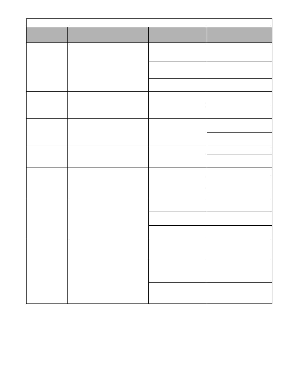
Table 6.1 Fault Displays and Processing (continued)
Digital
Operator Display
Description
Cause
Corrective Action
OL2
Inv Overload
Drive Overload
The Drive output current exceeded the
Drive’s overload curve.
The load was too large, or the
accel/decel times are too short.
Recheck the cycle time and the
size of the load as well as the times
set in C1-01 and C1-02.
The voltage of the V/F pattern
was incorrect for the
application.
Review the V/F pattern
parameters, E1-01 thru E1-13.
The size of the Drive was too
small.
Change to a larger size Drive.
OL3
Overtorque Det 1
Overtorque Detection 1
Drive output current > L6-02 for more than
the time set in L6-03 and L6-01 = 3 or 4.
Motor was overloaded.
Ensure the values in L6-02 and L6-
03 are appropriate.
Check application/machine status
to eliminate fault.
OL4
Overtorque Det 2
Overtorque Detection 2
Drive output current > L6-05 for more than
the time set in L6-06 and L6-04 = 3 or 4.
Motor was overloaded.
Ensure the values in L6-05 and L6-
06 are appropriate.
Check application/machine status
to eliminate fault.
OL7
HSB OL
High Slip Braking OL
The output frequency stayed constant for
longer than the time set in n3-04 during
high slip braking.
The inertia of the load is too
large.
Make sure the load is an inertial.
If possible, reduce the load
inertia.
OPR
Oper Disconnect
Digital Operator Connection Fault
Detected when the Digital Operator is
removed and the Drive is commanded to
run through the Digital Operator
(b1-02 = 0).
The Digital Operator was not
attached, or the Digital
Operator connector was
broken.
Attach the Digital Operator.
Check the Digital Operator
connector.
Verify the setting of o2-06.
OS
Overspeed Det
Motor Overspeed
Detected when F1-03 = 0 to 2 and
A1-02 = 1 or 3.
The motor speed feedback (U1-05)
exceeded the setting in F1-08 for a longer
time than the setting in F1-09.
Overshooting/Undershooting
was occurring.
Adjust the ASR settings in the C5
parameter group.
The reference was too high.
Check the reference circuit and
reference gain.
The settings in F1-08 and
F1-09 are not appropriate.
Check the settings in F1-08 and
F1-09.
OV
DC Bus Overvolt
DC Bus Overvoltage
The DC bus voltage has exceeded the trip
point.
208-240Vac: Trip point is 410Vdc
480Vac: Trip point is 820Vdc
High input voltage at R/L1,
S/L2 and T/L3.
Check the input circuit and reduce
the input power to within
specifications.
The deceleration time is set
too short.
Extend the time in C1-02 or other
active decel settings used such as
C1-04, C1-06, C1-08, or C1-09
(time).
Power factor correction
capacitors are being used on
the input or output to the
Drive.
Remove the power factor
correction capacitors.