Parameters a - 35, High slip braking, Monitor select – Yaskawa F7 Drive User Manual User Manual
Page 200: Table a.1 f7 parameter list (continued)
Parameters A - 35
High Slip Braking
n3-01
High Slip Braking
Deceleration Frequency
Width
HSB Decel Width
Sets how aggressively the Drive decreases the output frequency as
it stops the motor using high slip braking (HSB). If Overvoltage
(OV) faults occur during HSB, this parameter may need to be
increased.
1 to 20
5%
A
A
-
-
n3-02
High Slip Braking
Current Limit
HSB Current Ref
Sets the maximum current to be drawn during an HSB stop. Higher
n3-02 settings will shorten motor stopping times but cause
increased motor current, and therefore increased motor heating.
100 to
200
150%
A
A
-
-
n3-03
High Slip Braking Dwell
Time at Stop
HSB DwelTim@ Stp
Sets the amount of time the Drive will dwell at E1-09 (Minimum
Frequency) at the end of deceleration. If this time is set too low, the
machine inertia can cause the motor to rotate slightly after the HSB
stop is complete and the Drive output is shut off.
0.0 to
10.0
1.0sec
A
A
-
-
n3-04
High Slip Braking
Overload Time
HSB OL Time
Sets the time required for an HSB overload fault (OL7) to occur
when the Drive output frequency does not change for some reason
during an HSB stop. Normally this does not need to be adjusted.
30 to
1200
40sec
A
A
-
-
Monitor Select
o1-01
User Monitor Selection
User Monitor Sel
Selects which monitor will be displayed in the operation menu upon
power-up when o1-02 = 4.
4 to 45
6
A
A
A
A
o1-02
User Monitor Selection After
Power-Up
Power-On Monitor
Selects which monitor will be displayed upon
power-up.
1: Frequency Reference (U1-01)
2: Output Frequency (U1-02)
3: Output Current (U1-03)
4: User Monitor (set by o1-01)
1 to 4
1
A
A
A
A
o1-03
Digital Operator Display
Selection
Display Scaling
0 to
39999
0
A
A
A
A
o1-04
Setting unit for frequency
parameters related to V/F
characteristics
Display Units
Sets the setting units related to V/F pattern frequency related
parameters (E1-04, -06, -09, -11)
0: Hertz
1: RPM
0 to 1
0
-
-
-
A
o1-05
LCD Brightness
Adjustment
LCD Contrast
Sets the contrast of the Digital Operator LCD. A setting of “1” is the
lightest contrast and a setting of “5” is the darkest contrast.
0 to 5
3
A
A
A
A
Denotes that parameter can be changed when the Drive is running.
Table A.1 F7 Parameter List (Continued)
Parameter
No.
Parameter Name
Digital Operator Display
Description
Setting
Range
Factory
Setting
Control Method
V/F
V/F
w/PG
Open
Loop
Vector
Flux
Vector
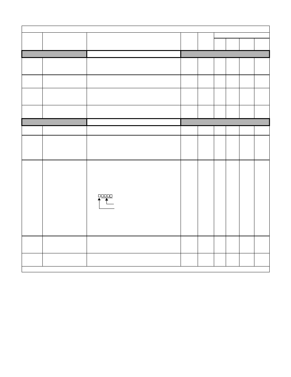
Sets the units of the Frequency References (d1-01 to
d1-17), the Frequency Reference Monitors (U1-01,
U1-02, U1-05), and the Modbus communication
frequency reference.
0: Hz
1: % (100% = E1-04)
2 to 39: RPM (Enter the number of motor poles).
40 to 39999: User display.
Set the number desired at maximum
output frequency.
4 digit number
Number of digits from the right of the
decimal point
Example 1: o1-03 = 12000, will result in frequency
reference from 0.0 to 200.0 (200.0 = Fmax).
Example 2: o1-03 = 21234, will result in frequency
reference from 0.00 to 12.34 (12.34 = Fmax).