Electrical installation 2 - 39, Wiring the pg-w2 – Yaskawa F7 Drive User Manual User Manual
Page 66
Electrical Installation 2 - 39
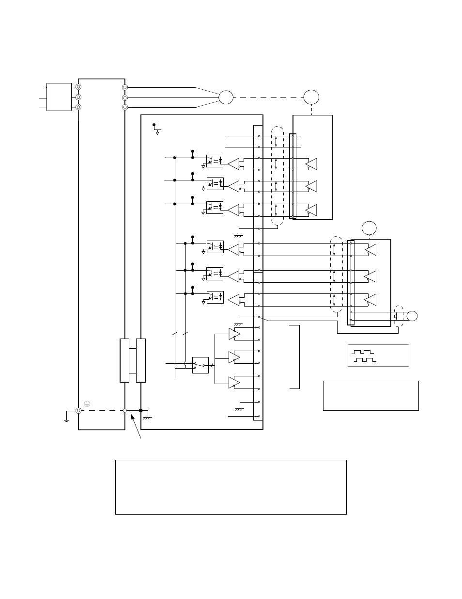
Wiring the PG-W2
Wiring examples are provided in Fig 2.23 for the PG-W2.
Fig 2.23 PG-W2 Wiring
R/L1
S/L2
T/L3
M
U/T1
V/T2
W/T3
Drive
PG-1
1
2
3
4
5
6
7
8
9
10
11
12
13
14
15
16
17
18
19
20
21
22
23
24
IP12
*
IG12
(+12V)
(0V)
12V
0V
P
P
P
P
P
P
P
TP1
(E)
12V
0V
P
+
Pulse A
Pulse B
Pulse Z
Pulse
IG5
(0V)
PG-2
4CN
4CN
12
TP3
TP7
TP6
TP5
TP4
TP8
3
Pulse
Out 1
3
Pulse A1
Pulse B1
Pulse Z1
Pulse A2
Pulse B2
Pulse Z2
TP2
Notes:
* Power supply for PG-1 (from PG-W2).
** PG-2 requires external power supply.
Pulse A
Pulse B
Ground wire
**
3
Pulse
Out 2
(E)
-
12V
Monitor
Outputs
(E)
(E)
PG-W2
Branch
Circuit
Protection
•
Shielded twisted-pair wires must be used for signal lines.
•
Do not use the PG-W2's power supply for anything other than the pulse generator (encoder).
Using it for another purpose can cause malfunctions due to noise.
•
The length of the pulse generator's wiring must not be more than 100 meters.
•
Do not use PG-W2 to supply both PG units.
- Tag Generator (30 pages)
- MP3300iec (82 pages)
- 1000 Hz High Frequency (18 pages)
- 1000 Series (7 pages)
- PS-A10LB (39 pages)
- iQpump Micro User Manual (300 pages)
- 1000 Series Drive Option - Digital Input (30 pages)
- 1000 Series Drive Option - CANopen (39 pages)
- 1000 Series Drive Option - Analog Monitor (27 pages)
- 1000 Series Drive Option - CANopen Technical Manual (37 pages)
- 1000 Series Drive Option - CC-Link (38 pages)
- 1000 Series Drive Option - CC-Link Technical Manual (36 pages)
- 1000 Series Drive Option - DeviceNet (37 pages)
- 1000 Series Drive Option - DeviceNet Technical Manual (81 pages)
- 1000 Series Drive Option - MECHATROLINK-II (32 pages)
- 1000 Series Drive Option - Digital Output (31 pages)
- 1000 Series Drive Option - MECHATROLINK-II Technical Manual (41 pages)
- 1000 Series Drive Option - Profibus-DP (35 pages)
- AC Drive 1000-Series Option PG-RT3 Motor (36 pages)
- Z1000U HVAC MATRIX Drive Quick Start (378 pages)
- 1000 Series Operator Mounting Kit NEMA Type 4X (20 pages)
- 1000 Series Drive Option - Profibus-DP Technical Manual (44 pages)
- CopyUnitManager (38 pages)
- 1000 Series Option - JVOP-182 Remote LED (58 pages)
- 1000 Series Option - PG-X3 Line Driver (31 pages)
- SI-EN3 Technical Manual (68 pages)
- JVOP-181 (22 pages)
- JVOP-181 USB Copy Unit (2 pages)
- SI-EN3 (54 pages)
- SI-ET3 (49 pages)
- MECHATROLINK-III (35 pages)
- EtherNet/IP (50 pages)
- SI-EM3 (51 pages)
- 1000-Series Option PG-E3 Motor Encoder Feedback (33 pages)
- 1000-Series Option SI-EP3 PROFINET (56 pages)
- PROFINET (62 pages)
- AC Drive 1000-Series Option PG-RT3 Motor (45 pages)
- SI-EP3 PROFINET Technical Manual (53 pages)
- A1000 Drive Option - BACnet MS/TP (48 pages)
- 120 Series I/O Modules (308 pages)
- A1000 12-Pulse (92 pages)
- A1000 Drive Software Technical Manual (16 pages)
- A1000 Quick Start (2 pages)
- JUNMA Series AC SERVOMOTOR (1 page)
- A1000 Option DI-101 120 Vac Digital Input Option (24 pages)