Alarm detection -10, Alarm detection, Diagnostics & troubleshooting 6 - 10 – Yaskawa F7 Drive User Manual User Manual
Page 135
Diagnostics & Troubleshooting 6 - 10
Alarm Detection
Alarms are Drive protection functions that do not operate the fault contact. The Drive will automatically return to its original
status once the cause of the alarm has been removed.
During an alarm condition, the Digital Operator display flashes and an alarm output is generated at the multi-function outputs
(H2-01 to H2-03) if programmed.
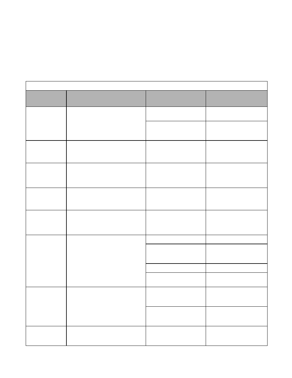
When an alarm occurs, take appropriate corrective action according to the table below.
Table 6.2 Alarm Displays and Processing
Digital
Operator Display
Description
Cause
Corrective Action
AEr
SI-T Address Err
<3021>
SI-T Station Number Setting Error
Station number of SI-T option board was
outside the setting range.
Station number setting error
Check the station number setting.
Refer to SI-T manual for details.
Circuit of SI-T option board is
faulty.
Check the communications
devices and signals.
Refer to SI-T manual for details.
BUS
Option Com Err
(Flashing)
Option Communication Error
After initial communication is
established, the connection was lost.
Connection is broken, master
controller has stopped
communicating.
Check all connections, verify all
user side software configurations.
CALL
SI-F/G ComCall
(Flashing)
Serial communication transmission
error.
Communication has not yet been
established.
Connection was not made
properly, or user software was
not configured to the proper
baud rate or configuration.
Check all connections, verify all
user side software configurations.
CE
MEMOBUS Com Err
(Flashing)
Modbus Communications Error
Enabled when H5-05 = 1 and H5-04 = 3.
Normal communication was not
possible for 2 seconds or longer
after control data was received.
Check the communications
devices and signals.
CyC
SI-T Cycle Err
<3021>
SI-T Communications Cycle Setting
Error
Communications cycle of SI-T option board
was out of range.
Communications cycle of SI-T
option board set in the master
controller was out of range.
Check the communication cycle
of SI-T option board set in master
controller.
Refer to SI-T manual for details.
DEV
Speed Deviation
(Flashing)
Excessive Speed Deviation
Detected when F1-04 = 3 and A1-02 = 1 or 3.
The speed deviation is greater than the
setting in F1-10 for longer than the setting
in F1-11.
The load was locked.
Reduce the load.
The acceleration time and
deceleration times were too
short.
Lengthen the acceleration and
deceleration times.
The load was too large.
Check the mechanical system.
The settings in F1-10 and F1-11
were not appropriate.
Check the settings in F1-10 and
F1-11.
DNE
Drive not Enable
(Flashing)
Detected when a multi-function digital
input (H1-01 to H1-06) is programmed for
6A: Drive enable.
The Drive does not have the enable
command when the run command is
applied. This alarm stops the motor.
Enable command was lost while
Drive was running.
Check the input terminal
programmed for enable
command.
The Run command was applied
prior to the enable signal.
Apply and maintain the enable
command before applying the run
command.
EF
External Fault
Both the forward and the reverse run
commands are input simultaneously for
500ms or more. This alarm stops the motor.
An external forward and
reverse command were input
simultaneously.
Check external sequence logic,
so only one input is received at a
time.