Electrical installation 2 - 32, Pg-a2, Wiring the pg-a2 – Yaskawa F7 Drive User Manual User Manual
Page 59
Electrical Installation 2 - 32
PG (Encoder) Feedback Board Terminal Specifications and Wiring Examples
PG-A2
The terminal specifications for the PG-A2 are given in Table 2.18.
Wiring the PG-A2
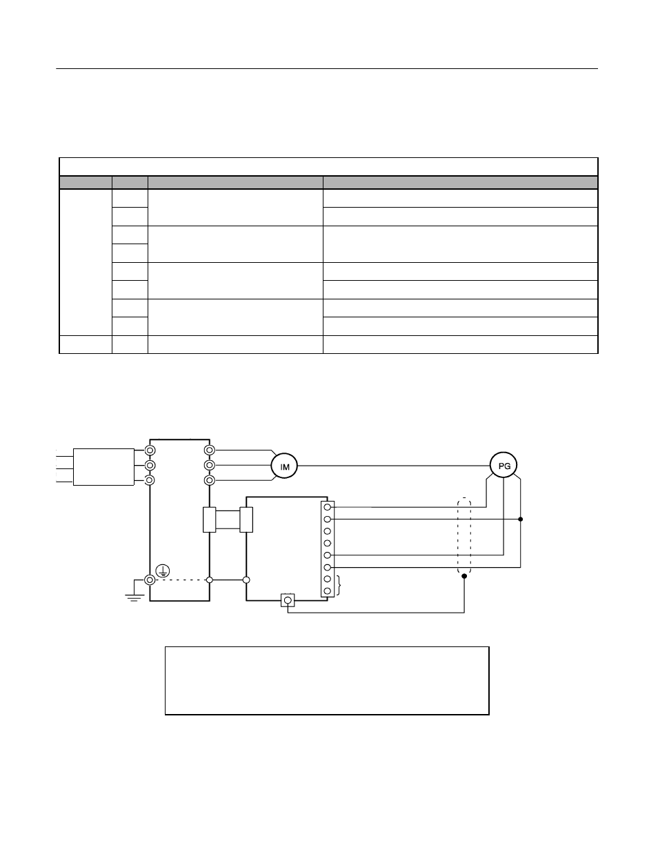
Wiring examples are provided in the following figures for the PG-A2.
Fig 2.17 PG-A2 Open-Collector Input Wiring - Sourcing PG
Table 2.18 PG-A2 Terminal Specifications
Terminal
No.
Contents
Specifications
TA1
1
Power supply for pulse generator
12Vdc (±5%), 200mA max.
2
0Vdc (GND for power supply)
3
+12V/open collector switching terminals
Terminals for switching between12Vdc voltage input and open
collector input. For open collector input, short across 3 and 4.
4
5
A-phase pulse input terminals
H: +4 to 12V; L: +1V max. (Maximum response frequency: 30kHz)
6
Pulse input common
7
A-phase pulse monitor output terminals
12Vdc (±10%), 20mA max.
8
Pulse monitor output common
TA2
(E)
Shield connection terminal
-
+12Vdc power supply
0Vdc power supply
12Vdc voltage input (A phase)
Pulse 0Vdc
Pulse monitor output
R/L1
V/L2
W/L3
U/T1
V/T2
W/T3
4CN
4CN
E
E
1
2
3
4
5
6
7
8
TA1
TA2 (E)
PG-A2
Branch
Circuit
Protection
Drive
•
Shielded twisted-pair wires must be used for signal lines.
•
Do not use the PG-A2's power supply for anything other than the pulse generator (encoder).
Using it for another purpose can cause malfunctions due to noise.
•
The length of the pulse generator's wiring must not be more than 100 meters.