Warning, Electrical installation 2 - 15 – Yaskawa F7 Drive User Manual User Manual
Page 42
Electrical Installation 2 - 15
Braking Transistor Unit(s) and Remote Mount Resistor Unit(s) Installation
(for F7U2022 thru F7U2110 and F7U4022 thru F7U4300)
Since the Remote Mount Resistor Unit generates heat during dynamic braking operation, install it to a noncombustible surface
in a location away from other equipment.
Select mounting locations for Braking Transistor Unit(s) and Remote Mount Resistor Unit(s) so that wiring between the Drive
and the Braking Transistor Unit is 16 feet (5m) or less, and the wiring between each Braking Transistor Unit and its associated
Remote Mount Resistor Unit, is less than 33 feet (10m).
1. Mount the Braking Transistor Unit(s) on a vertical surface. The Braking Transistor Unit requires a minimum of 1.18 inches
(30mm) clearance on each side and a minimum 3.94 inches (100mm) clearance top and bottom. Attach the Remote Mount
Resistor Unit maintaining a minimum 1.97 inches (50mm) clearance on each side and a minimum 7.87 inches (200mm)
clearance on top.
2. In each Braking Transistor Unit, set the nominal line voltage jumper plug to the correct setting for the installation; this is
factory set at the 220V/440V/575V position. To access jumper plugs, remove the plastic cover.
3. If multiple Braking Transistor Units are being installed, the unit closest to the Drive should have the Slave/Master jumper
plug set to the “Master” position (factory setting); all others must have this jumper plug set to the “Slave” position.
4. If a single Braking Transistor Unit and Remote Mount Resistor Unit are being installed, connect them to the Drive and
external control circuitry according to the chart below and Fig 2.7.
5. Power leads for the Remote Mount Resistor Unit generate high levels of electrical noise - these power leads must be
grouped separately from all other leads.
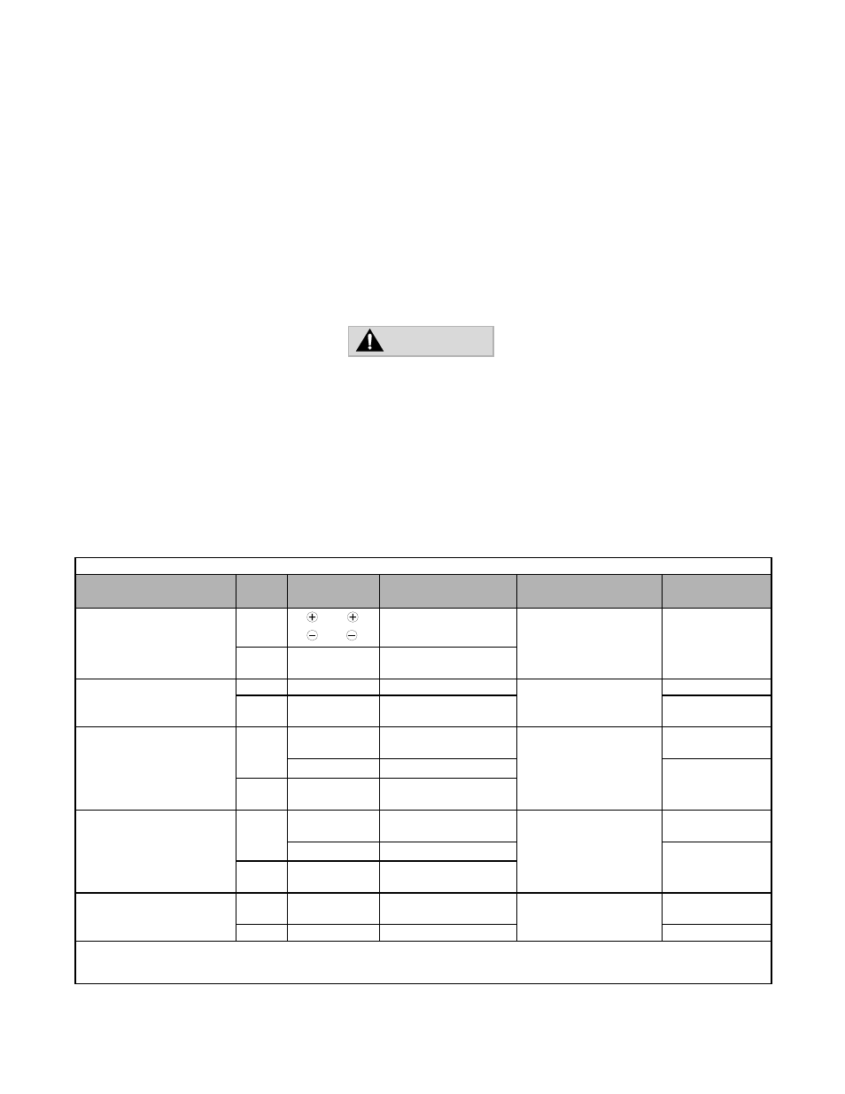
Table 2.10 Wire Size for Remote Mount Resistor Unit and Braking Transistor Unit
Name
Circuit
Terminals
Wire Size AWG (mm
2
)
Wire Type
Terminal Screw
Braking Transistor Unit
(Models CDBR-2015B,
-2022B, -4030B, -4045B)
Main
0
0
12-10 (3.5-5.5)
600V vinyl sheathed wire
or equivalent
M4
Control
1 2 3
4 5 6
18-14 (0.75-2)
Braking Transistor Unit
(Model CDBR-2045, -4090)
Main
P, Po, N, B
12-10 (3.5-5.5)
600V vinyl sheathed wire
or equivalent
M5
Control
1 2 3
4 5 6
18-14 (0.75-2)
M4
Braking Transistor Unit
(Model CDBR-2110)
Main
P, Po, N, B
4 (22)
8-6 (8-14) *1
600V vinyl sheathed wire
or equivalent
M6
r
s
12-10 (3.5-5.5)
M4
Control
1 2 3
4 5 6
18-14 (0.75-2)
Braking Transistor Unit
(Model CDBR-4220)
Main
P, Po, N, B
4 (22)
8-6 (8-14) *1
600V vinyl sheathed wire
or equivalent
M6
r
s
12-10 (3.5-5.5)
M4
Control
1 2 3
4 5 6
18-14 (0.75-2)
Braking Resistor Unit
(Model LKEB-F )
Main
B P
12-10 (3.5-5.5)
600V vinyl sheathed wire
or equivalent
M4
(M5) *2
Control
1 2
18-14 (0.75-2)
M4
*1 For wire size of 8-6 (8-14), use UL1283 heat-resistant vinyl-insulated wire or equivalent.
*2 M4 for Models LKEB-20P7 to -27P5 or -40P7 to -4015.
M5 for Models LKEB-2011 to -2022 or -4018 to -4045.
WARNING
• Be sure to set the nominal line voltage selection jumper to match the level of the AC supply being applied to the Drive.
• Failure to do so may result in improper operation.