Parameters a - 33, Torque limit, Hardware protection – Yaskawa F7 Drive User Manual User Manual
Page 198: Table a.1 f7 parameter list (continued)
Parameters A - 33
L6-02
Torque Detection Level 1
Torq Det 1 Lvl
Sets the Overtorque/Undertorque detection level as a percentage of
Drive rated current or torque for torque detection 1. Current
detection for A1-02 = 0 or 1. Torque detection for A1-02 = 2 or 3.
0 to 300
150%
A
A
A
A
L6-03
Torque Detection Time 1
Torq Det 1 Time
Sets the length of time an Overtorque/Undertorque condition must
exist before torque detection 1 recognized by the Drive.
0.0 to
10.0
0.1sec
A
A
A
A
L6-04
Torque Detection
Selection 2
Torq Det 2 Sel
Determines the Drive's response to an Overtorque/Undertorque
condition. Overtorque and Undertorque are determined by the
settings in parameters L6-05 and L6-06. The multi-function output
settings “18” and “19” in the H2-
parameter group are also
active if programmed.
0: Disabled
1: OL4 at Speed Agree - Alarm (Overtorque Detection only active
during Speed Agree and Operation continues after detection).
2: OL4 at RUN - Alarm (Overtorque Detection is always active and
operation continues after detection).
3: OL4 at Speed Agree - Fault (Overtorque Detection only active
during Speed Agree and Drive output will shut down on an OL4
fault).
4: OL4 at RUN - Fault (Overtorque Detection is always active and
Drive output will shut down on an OL4 fault).
5: UL4 at Speed Agree - Alarm (Undertorque Detection is only
active during Speed Agree and operation continues after
detection).
6: UL4 at RUN - Alarm (Undertorque Detection is always active
and operation continues after detection).
7: UL4 at Speed Agree - Fault (Undertorque Detection only active
during Speed Agree and Drive output will shut down on an OL4
fault).
8: UL4 at RUN - Fault (Undertorque Detection is always active and
Drive output will shut down on an OL4 fault).
0 to 8
0
A
A
A
A
L6-05
Torque Detection Level 2
Torq Det 2 Lvl
Sets the Overtorque/Undertorque detection level as a percentage of
Drive rated current or torque for torque detection 2. Current
detection for A1-02 = 0 or 1. Torque detection for A1-02 = 2 or 3.
0 to 300
150%
A
A
A
A
L6-06
Torque Detection Time 2
Torq Det 2 Time
Sets the length of time an Overtorque/Undertorque condition must
exist before torque detection 2 is recognized by the Drive.
0.0 to
10.0
0.1sec
A
A
A
A
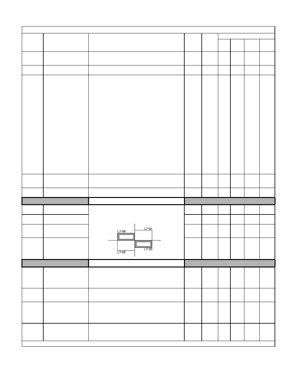
Torque Limit
L7-01
Forward Torque Limit
Torq Limit Fwd
Sets the torque limit value as a percentage of the motor rated torque.
Four individual quadrants can be set.
0 to 300
200%
-
-
A
A
L7-02
Reverse Torque Limit
Torq Limit Rev
0 to 300
200%
-
-
A
A
L7-03
Forward Regenerative Torque
Limit
Torq Lmt Fwd Rgn
0 to 300
200%
-
-
A
A
L7-04
Reverse Regenerative Torque
Limit
Torq Lmt Rev Rgn
0 to 300
200%
-
-
A
A
Hardware Protection
L8-01
Internal Dynamic Braking
Resistor Protection
Selection
DB Resistor Prot
Selects the DB protection only when using 3% duty cycle heatsink
mount Yaskawa braking resistor. This parameter does not enable or
disable the DB function of the Drive.
0: Not Provided
1: Provided
0 to 1
0
A
A
A
A
L8-02
Overheat Alarm Level
OH Pre-Alarm Lvl
When the cooling fin temperature exceeds the value set in this
parameter, an overheat alarm (OH) will occur.
50 to
130
Varies
by
kVA
A
A
A
A
L8-03
Overheat Pre-Alarm
Operation Selection
OH Pre-Alarm Sel
Selects the Drive operation upon an OH pre-alarm detection.
0: Ramp to Stop
1: Coast to Stop
2: Fast-Stop
3: Alarm Only
0 to 3
3
A
A
A
A
L8-05
Input Phase Loss
Protection Selection
Ph Loss In Sel
Selects the detection of input current phase loss, power supply volt-
age imbalance, or main circuit electrostatic capacitor deterioration.
0: Disabled
1: Enabled
0 to 1
1
A
A
A
A
Denotes that parameter can be changed when the Drive is running.
Table A.1 F7 Parameter List (Continued)
Parameter
No.
Parameter Name
Digital Operator Display
Description
Setting
Range
Factory
Setting
Control Method
V/F
V/F
w/PG
Open
Loop
Vector
Flux
Vector
Output torque
Positive torque
Reverse
Negative torque
No. of
motor
rotations
Regen. state
Regen. state
Forward