Hardware setup, Configuration, Power – Measurement Computing WaveBook rev.3.0 User Manual
Page 89: Re setup…… 4-5, 28 vdc mode
WaveBook User’s Manual,
6-21-99
System Power & Assembly 4-5
28 VDC Mode
The 28 VDC mode actually provides both 14 VDC and 28 VDC. Loop currents for two-wire, 4-20 mA
transmitters (1.7 A-hr) require 28 VDC. The battery run-time ranges from 1 to 6 hours, depending on
system configuration. In this mode, 14 VDC is used for unregulated bridge excitation (for bridge-
configured sensors, such as load cells), and power to WBK expansion products.
Unless you need 28 V, leave the unit in the 14 VDC mode. Use of the 28 VDC mode results in
a lower runtime, as only one battery pack can be used for 14 VDC. When in the 14 VDC mode,
both packs are used in parallel, resulting in a longer runtime for the same application.
Hardware Setup
Configuration
The only configuration option is the choice of modes (14 VDC, or 28 VDC). If you do not need 28 V, leave
SW2 in the default position.
If you are using a pre-owned DBK30A, or are unsure of the mode selected, use the
following steps to check SW2’s position. Note that new units are always shipped with SW2
selected to the 14 VDC mode.
Internal switch SW2 is located on the printed circuit board, near the front center of the unit. To change or
verify the mode:
1. Remove DBK30A’s cover by removing one screw and sliding the cover forward until it separates from
the module.
2. Look near the front center of the circuit board and locate slide switch SW2.
3. Check SW2’s selection. The silkscreen indicates the 14 and 28 VDC positions.
4. Change the selection, if required. If you do not need 28 V, SW2 should be in the default position
(14 VDC).
5. Replace the top cover, and secure with screw.
Power
Connection. The figure shows the pinout for the POWER OUT DIN5 connector.
The 28 V pin is only active in the 28 VDC mode; however, the 14 V pin is active
regardless of the mode selected.
Cable CA-115 is included in the DBK30A package. The cable connects to
DBK30A’s POWER OUT connector and WaveBook’s POWER IN connector.
The cable can be used to daisy-chain a DBK30A unit to a WBK expansion module.
DIN5 Power Out
+14 V
+28 V
GND
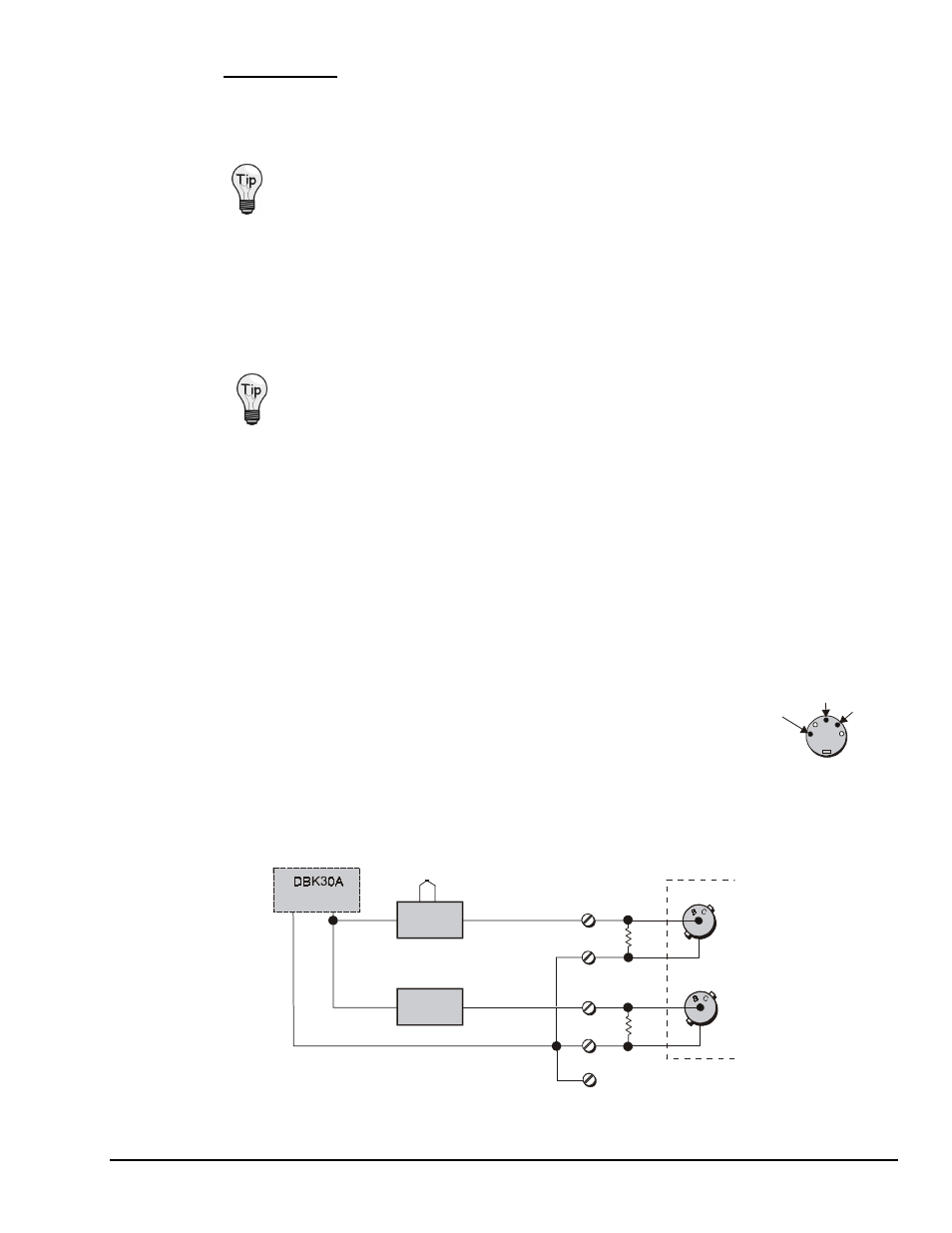
28 VDC Mode. The primary purpose of the 28 VDC mode is to provide power for external loop
transmitters. The hookup is simple, as shown below.
WaveBook
2-Wire
T/C XMTR
2-Wire
Flow XMTR
T/C
4-20 mA
4-20 mA
COM
+
+
250
Ω
250
Ω
N
N
Connecting Loop Transmitters