Connection, Warning – Measurement Computing WaveBook rev.3.0 User Manual
Page 51
WaveBook User’s Manual,
ch03B 6-23-99
WBK Expansion Options, WBK15 3-19
Connection
WARNING
WARNING
WARNING
WARNING
Electric shock hazard! De-energize circuits connected to WBK15 before changing the
wiring or configuration. Failure to do so could lead to injury or death due to electric
shock.
Signals are connected by screw-terminal signal plugs that plug into the 4-pin jacks on WBK15’s front panel
(see figure).
-EXC Negative excitation output - only used on strain-gage type modules
- Negative signal input
+ Positive signal input
+EXC Positive excitation output - only used on strain-gage type modules
-EXC
- +
+EXC
Signal Connection Jacks (per channel)
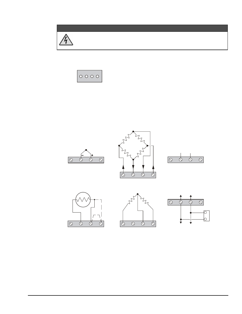
Input signals (and excitation leads) must be wired to the plug-in terminal blocks. Eight 4-terminal blocks
accept up to 8 inputs.
Terminal blocks are connected internally to their corresponding signal conditioning module. The terminal
blocks accept up to 14-gage wire into quick-connect screw terminals. Each type of input signal or
transducer (such as a thermocouple or strain gage) should be wired to its terminal block as shown in the
figure below. Wiring is shown for RTDs, thermocouples, 20mA circuits, mV/V connections, and for full-
and half-bridge strain gages.
+EXC
+Vin
-Vin
-EXC
SIG H
SIG L
mV and V Connection
4-Wire
3-Wire
2-Wire
+EXC
+Vin
-Vin
-EXC
RTD Connection
+EXC
+Vin
-Vin
-EXC
Half-Bridge
Strain-Gage Connection
-EXC
+EXC
+Vin
-Vin
A
C
13
62
20 Ohm
Plug-In Resistor
(SC-AC-1362)
On-Board Socket
4-20 mA
Connection
Full-Bridge Strain-Gage Connection
+EXC
+Vin
-Vin
-EXC
_
+
Thermocouple
Connection
+EXC
+Vin
-Vin
-EXC
Typical Signal Connections