Wavebook/516, Analog signal processing, Digital i/o signal processing – Measurement Computing WaveBook rev.3.0 User Manual
Page 141: Book/516…8-7, Ng…… 8-7
WaveBook User’s Manual.
6-24-99
Theory of Operation 8-7
WaveBook/516
Analog Signal Processing
Each channel’s input buffer has its own differential amplifier. These amplifiers have a flat frequency
response to 500 kHz. This frequency response allows digitization of broadband signals up to the A/D
Converter’s Nyquist frequency. For dynamic signal measurements, a five-pole LPF [Butterworth, anti-alias
low-pass filter] optionally follows each differential amplifier. Filter cut-off frequency is preset to 20kHz.
This setting is ideal for the majority of acoustic, shock, and vibration applications.
Digital I/O Signal Processing
WaveBook/516 supports 16 high-speed digital inputs within the data acquisition. When the data acquisition
is stopped, the port can be used as a general-purpose I/O port.
During Acquisition:
16 bit input
With Acquisition Stopped:
16 bit input
16 bit output
8 bit addressed I/O with 32 available addresses
When WaveBook is not acquiring data, the daqIORead and daqIOWrite commands may be used to
read and write bytes (respectively) at any one of the 32 addresses; or directly read [or write] 16 bit words.
DB25 pinout information is provided on the following page.
If the digital I/O port is only being used to sample the digital inputs during acquisitions, connect the
digital signals to the digital I/O port data lines.
If the digital I/O port is to be used for addressed I/O (using daqIORead and daqIOWrite), then the
digital signals must conform to the timing requirements shown in the digital I/O port-timing diagram. Refer
to “Digital I/O Port Timing Diagram,” on the preceding page.
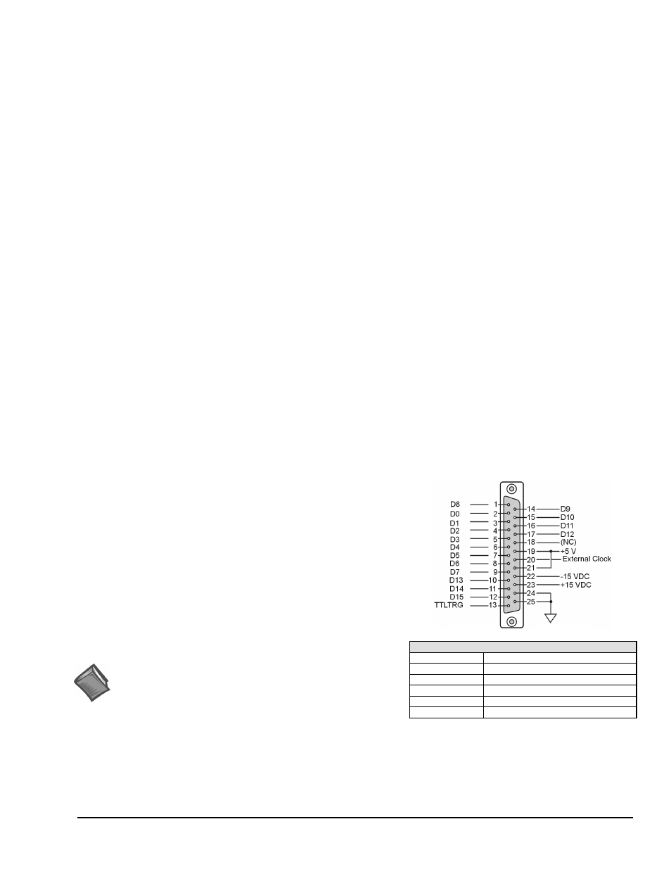
Digital I/O Connection (WaveBook/516 Only)* 16-bit mode
Digital I/O Connections, WaveBook/516
With the WaveBook/516 series (16-bit mode), the following signals
are present on the DB25F high-speed digital I/O connector.
• 16 High-Speed Digital I/O Lines (D0 through D15)
• TTL Trigger Input (TTLTRG)
• +15 V (pin 23), -15 V (pin 22), 50 mA max. (each)
• two +5 V (pin 19 and pin 21), 250 mA max. (total)
• External Clock (pin 20)
• two Digital Grounds (pins 24 and 25)
To sample just 16 digital input signals, connect them directly to
the digital I/O data lines. D15 is the most significant bit, and D0
is the least.
D0 – D15
High Speed Digital I/O data lines
TTLTRG
TTL trigger input
External Clock
16 bit mode, read/write strobe
+5 VDC
250 mA maximum
+15,-15 VDC
50 mA maximum (each)
Reference Note:
For WaveBook/516’s 8-bit mode pinout, refer to page 8-5.
Digital Grounds
Pins 24 and 25