Bridge configuration, Amplifiers, Offset source – Measurement Computing WaveBook rev.3.0 User Manual
Page 55: Filters, Output selection, Front & rear panels
WaveBook User’s Manual,
ch03B 6-23-99
WBK Expansion Options, WBK16 3-23
Bridge Configuration
The strain gage is connected to the amplifiers through the Bridge Completion and Shunt Cal Network. This
network consists of user installed resistors for bridge completion. Several combinations of resistors and
three different shunt values may be installed simultaneously. External connector tie points and the
programmable Input Configuration & Cal MUX determine the actual configuration in use. Once the
network is fully configured, most bridge configurations and resistances can be accommodated without re-
opening the box. The shunt resistors allow each bridge to be put into a known imbalance condition for
setting or verifying channel calibration. Shunt calibration allows a full-scale gain to be set without
physically loading the bridge. The Hardware Setup section, beginning on page 3-24, contains detailed
information. The section also includes discussion of the CN-189, DB9 Adapter option.
Amplifiers
Each channel has an amplifier consisting of two series connected stages. The instrumentation amplifier
(PGIA) has programmable gains of 1, 10, 100, and 1000. A programmable gain amplifier (PGA) follows,
with a gain range of 1 to 20 in 28% steps. This results in a combined programmable gain range of 1 to
20,000 in 28% steps. The optimal gain is automatically determined during the gage calibration process.
Offset Source
A low-drift, programmable offset voltage source with a range of ±3.0 V is used to balance the bridge during
the gage calibration process. This offset source will correct for mismatched bridge resistors and quiescent
loads of the strain gage and still retain the full dynamic range.
Auto-zero removes the static portion of the strain load and zeros the input to compensate for any input drift.
Because this is done electronically, zeroing is independent of the user. Simply select the channels that are to
be auto-zeroed and the WBK16 will complete the task automatically.
Filters
Two different 4-pole Butterworth low-pass noise rejection filters are selectable through software by the
Output Selection MUX. The filters have a nominal cutoff frequency of 10 Hz and 1 kHz. Four SIP resistor
networks allow you to determine two cutoff frequencies. See the Hardware Configuration section for
details. If full bandwidth is required, a filter bypass mode is software selectable.
Output Selection
An AC coupling circuit with a 1-Hz cutoff frequency can be software selected by the MUX. This MUX can
also select an Inverting Amplifier for proper output signal polarity. The Inverter avoids having to rewire the
gage if the polarity is reversed. Note that the Inverter option is not available for AC coupling modes.
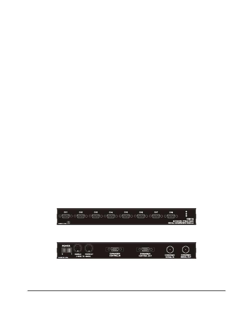
Front & Rear Panels
WBK16’s front panel has the following connectors and indicators as shown:
ACTIVE
POWER
READY
• 8 DB-9 connectors for bridge input
• 3 LEDs to indicate system status (Active, Ready, Power)
The rear panel has the power switch and the following connectors as shown:
• 2 5-pin DIN5 connectors for power input and power pass-through
• 1 DB-15M expansion control input connector
• 1 DB-15F expansion control output connector
• 2 BNC connectors for analog expansion in and out