Calibration example – Measurement Computing WaveBook rev.3.0 User Manual
Page 73
WaveBook User’s Manual,
ch03C 6-21-99
WBK Expansion Options, WBK16 3-41
Calibrating a Sensor Using the Sensor Calibration Program
Before proceeding with calibration, remember to enter your password. The password
must be entered before channel parameters can be changed.
Unless all of the parameters (for each channel to be calibrated) are accurately entered
into the spreadsheet, the calibration will produce incorrect results.
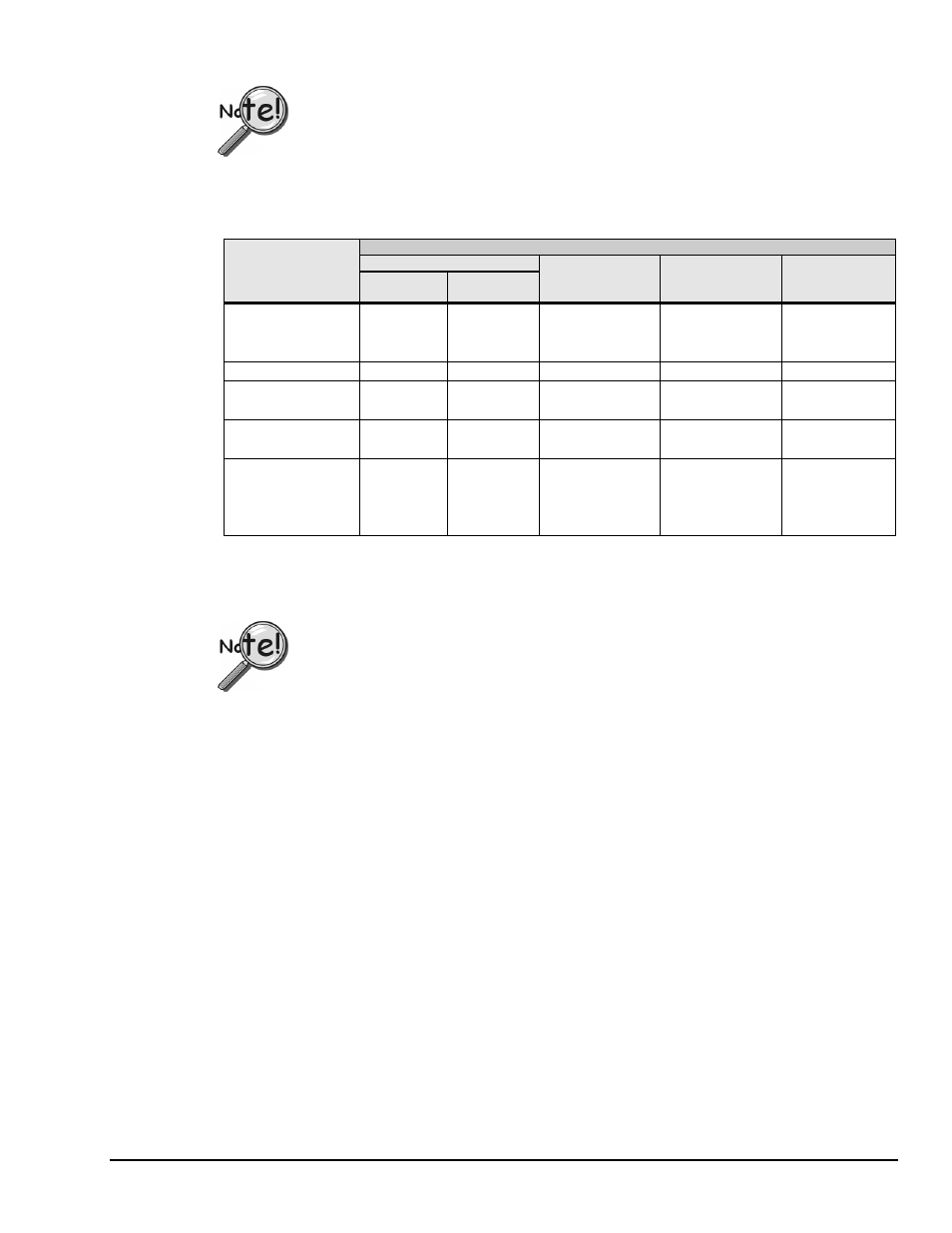
The WBK16 sensor calibration program uses four basic methods of calibration: Name Plate, Shunt, 2-Point
Manual, and 2-Point Automatic. All four methods require values for the excitation voltage, maximum
applied load, and quiescent/tare for all sensor types.
Calibration Methods
Name Plate
Required
Calibration
Parameters
Strain Gage
Load Cell or
Transducer
Shunt
2-Point Manual
2-Point
Automatic
Excitation Voltage
3
3
3
3
3
Max. Applied Load
3
3
3
3
3
Quiescent/Tare
3
3
3
3
3
Gage Factor
3
Sensitivity
3
Full Rated Load
3
Shunt Load Value
3
Bridge Resistance
3
Point 1 (mV Input)
3
3
Point 1 (Units Input)
3
3
3
Point 2 (mV Input)
3
Point 2 (Units Input)
3
3
To use any of these calibration methods, enter the appropriate values into the required spreadsheet columns
of the WBK16 Sensor Calibration window, as listed above, and click on the Calibrate Enabled Channels
button on the toolbar.
In 2-Point Manual calibration, a message box prompts you to apply the first load. When
prompted, apply the load and click the OK button. A second message box will prompt
you to apply the second load. When prompted, apply the second load and click OK.
Saving a Calibration File. After calibrating the enabled channels, a message box asks if you want to save
the changes. Click on the Yes button to save the calibration and a dialog box will appear. If you choose not
to save the changes at this time, another message will appear asking if you want to save the changes when
you click on the Return to WaveView button on the tool bar. Click on the Yes button to save these changes
and a dialog box will appear. The most recently saved calibration file will be recorded in the
WAVEVIEW.CFG
default configuration file and will be loaded into WaveView whenever a new session is
started. The current configuration can also be saved from the toolbar or File menu item.
Calibration Example
The following example uses Name Plate calibration with a load cell.
Load cells come with a mV/V specification (frequently referred to as sensitivity) which means for each volt
of excitation at maximum load, the load cell will output a specific millivolt level.
Consider a 3000-pound load cell rated at 3 mV/V using 10 V of excitation. When the load cell is used, a 10-
pound platform will be placed on it. Although the load cell is rated at 3000 pounds, 1500 pounds is the
maximum load that will ever be applied for this example.
According to the previous table, the required parameters for a Name Plate calibration when a load cell is
used are excitation voltage, maximum applied load, quiescent/tare, sensitivity and full rated load. From the
above data we know the following parameters:
• Excitation Voltage = 10 volts
• Maximum Applied Load = 1500 pounds
• Quiescent Tare = 10 pounds
• Sensitivity = 3 mV/V