Wbk14 - dynamic signal input module, Description, Current source – Measurement Computing WaveBook rev.3.0 User Manual
Page 42
3-10 WBK14, WBK Expansion Options
WaveBook User’s Manual
WBK14 - Dynamic Signal Input Module
Description
The WBK14 is a dynamic analog signal input module for the WaveBook data acquisition system. The
WBK14 provides a complete system to interface to piezoelectric transducers that include accelerometers,
microphones, force/pressure transducers, and others.
Reference Note: An accelerometer tutorial begins on page 3-13.
Each WBK14 channel has a:
• current source for transducer biasing
• high-pass filter
• programmable gain amplifier
• anti-aliasing low-pass filter
• simultaneous sample-and-hold (SSH) amplifiers
The gain, filter cut-off frequencies and current biasing levels are software programmable.
WBK14 includes a built-in programmable excitation source. This source stimulates dynamic systems for
transfer function measurements, and serves as a reference signal for calibration.
N
N
N
µP and
Control Logic
EEPROM
OUT
IN
Expansion
Unit Control
Buffer
MUX
PGA
-
+
One of 8 channels
Channel
Input
BNC
Transducer Bias
Current Source
Multiplexed
Analog Output
to WaveBook
Programmable
Anti-aliasing
Low-Pass Filter
Sample
& Hold
Programmable
Low-Pass Filter
Phase Equalizer
0.1 Hz
High-Pass
Filter
10 Hz
High-Pass
Filter
Expansion
Signal
BNC
MUX
MUX
N
N
OSC
External
Clock
BNC
Timebase
Control
PLL
Filter
Offset
DAC
Amplitude
DAC
Excitation
Source
Output
BNC
DC/DC
Converter
10 to 30 VDC Input power
from AC adapter, DBK30A,
DBK34, or 12-V car battery, etc
Power Supply
+5
- 5
+15
- 15
Fuse
ON/OFF
Switch
DIN5s can be
daisy-chained
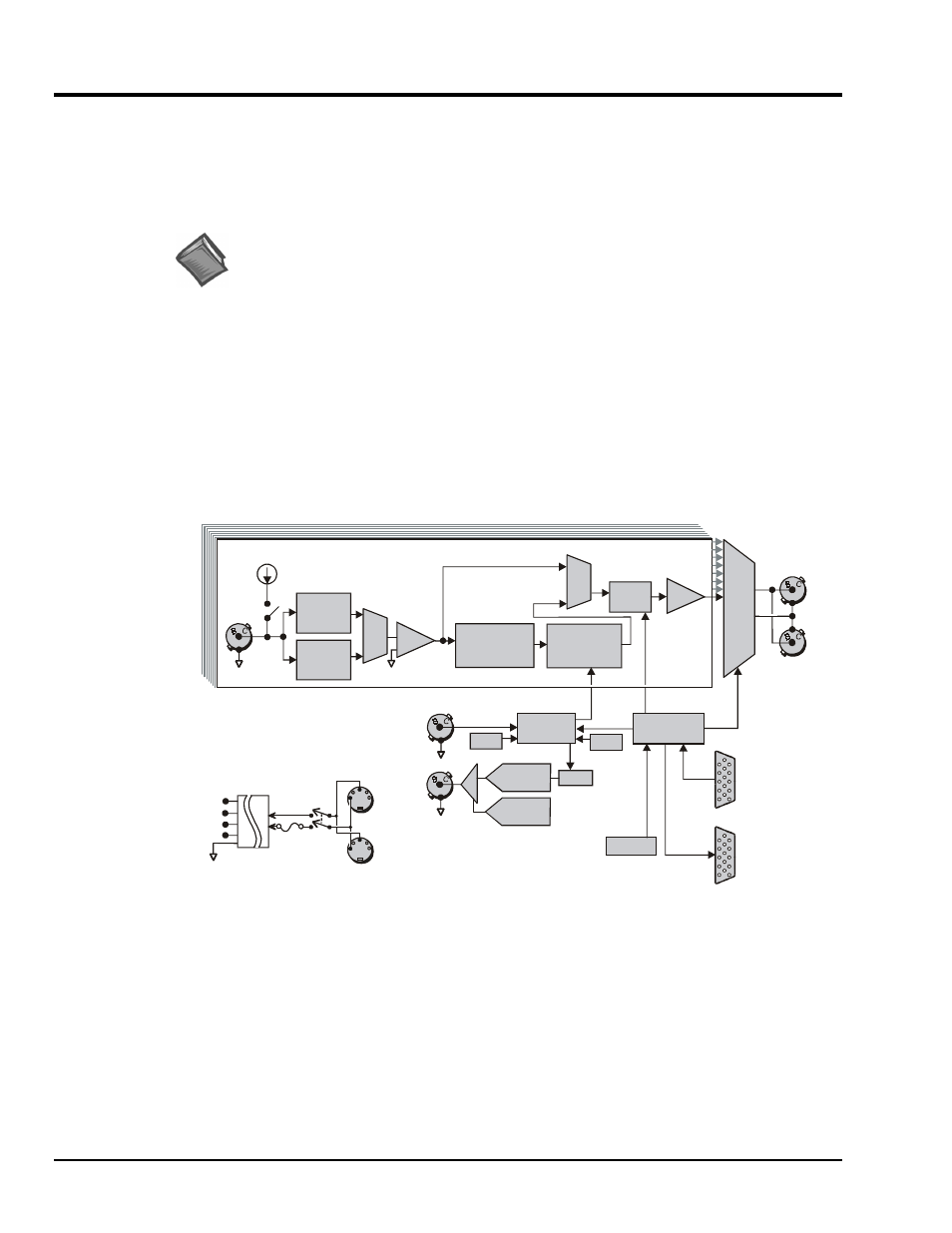
WBK14 Block Diagram
Current Source
WBK14 provides constant current to bias ICP transducers. Two current levels (2 mA or 4 mA) with
voltage compliance of 27 V can be selected via software. The bias current is sourced through the center
conductor of a coaxial lead and returns to the WBK14 by the outer conductor. The output impedance is
larger than 1 M
Ω and presents virtually no loading effect on the transducer’s output. For applications that
do not require bias, the current source can be removed from the BNC input by opening a relay contact.
The current sources are applied to (or removed from) the input in channel groups of two; i.e.,
channels 1-2, 3-4, 5-6, 7-8.